
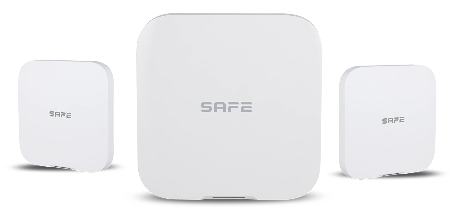
Smart control panel SAFE 100HUB-WLRF provides complete management of all connected devices of the FireSAFE fire and safety system and alerts the user in good time to possible risks, such as a carbon monoxide leak, detection of flammable or explosive gases, the threat of fire or flooding. It allows all FireSAFE safety elements to be linked using the function CONNECTED, continuously monitors their status and, in the event of any danger, immediately informs the user through the FireSAFE mobile app. The system uses technologies such as flame detection, temperature measurement, video verification, intelligent warnings or automation.
Foreword
General
This user manual describes the installation, functions and operation of the SAFE 100HUB-WLRF Hub. Read the manual carefully before using the device and keep it for future reference.
Safety instructions
The following signal words may appear in the user manual:
| Signal word | Meaning |
|---|---|
| NEBEZPEČÍ | Indicates a high potential hazard which, if not avoided, may result in death or serious injury. |
| VAROVÁNÍ | Indicates a medium or low potential hazard which, if not avoided, could result in minor or moderate injury. |
| UPOZORNĚNÍ | Indicates a potential risk which could lead to property damage, data loss, reduced performance or an unpredictable result. |
| TIP | Provides methods to help you solve a problem or save time. |
| POZNÁMKA | Provides additional information, such as emphasis or a supplement to the text. |
Revision history
| Version | Revision content | Release date |
|---|---|---|
| V1.0.0 | First release. | September 2026 |
| V1.0.1 | Colours according to the FireSAFE brand (red). | October 2026 |
About the manual
- The user manual serves as a reference only. Minor differences may occur between the information provided and the product.
- We are not liable for damage resulting from use of the product in a manner that is not in accordance with the instructions in the user manual.
- The manual will be updated in line with the current laws and regulations of the relevant countries. For detailed information, see the printed user manual or visit our website. The electronic and printed versions may differ in minor details.
- All designs and software may be changed without prior written notice. As a result of product updates, certain differences may appear between the product and the information in the manual. The latest version of the software and supplementary documentation is available from customer service.
- Printing errors or deviations may occur in the description of functions, operations and technical data. In case of doubt or dispute, we reserve the right of final interpretation.
- All trademarks, registered trademarks and company names in the manual are the property of their respective owners.
- If any problems occur while using the device, visit our website, or contact your supplier or customer service.
Privacy notice
The Hub stores the system event history and – if an SD memory card is inserted – also event logs. As a user of the device or a data controller, you are obliged to handle the data obtained in accordance with local privacy protection laws and regulations and to protect the legitimate rights and interests of other persons.
Important precautions and warnings
This section contains information on the correct handling of the product, risk prevention and prevention of property damage. Read it carefully before using the device and follow the instructions provided while using it.
Operating requirements
- Before using the device, make sure the Hub is correctly connected to the power supply and the internet network.
- Do not pull the power cable out of the device while the device is connected to the mains.
- Use the device only within its rated power range.
- Use the device in accordance with the instructions given for the operating environment.
- Transport, use and store the device under the humidity and temperature conditions permitted by the manufacturer.
- Do not expose the product to water or moisture, or to dripping or splashing water.
- Do not insert any objects into the ventilation openings of the product, do not cover the product, and take care to prevent water or other liquid from entering the device.
- Do not disassemble the device.
Installation requirements
Incorrect installation and operation of this device will prevent it from functioning correctly and consequently from responding to danger. Connect the device to the power supply before switching it on. Before connecting the device to the mains or a power source:
- Strictly follow local electrical safety standards and make sure that the voltage in the area is stable and meets the device's power supply requirements specified by the manufacturer.
- Do not connect the device to more than one power source. Otherwise the device could be damaged and the warranty lost.
- When working at height, follow all safety procedures and use the required protective equipment intended for this purpose.
- Do not expose the product to direct sunlight, extreme cold, humidity or sudden changes in temperature.
- Installation and handling of this device must always comply with local electrical safety requirements, requirements for protection against electric shock and other relevant regulations.
- Install the device in a well-ventilated place and do not block its ventilation.
- Use only cables and power adapters approved and supplied by the device manufacturer to connect to the power source.
- The power supply and accessories must meet the requirements of the ES1 and IEC 62368-1 standards and must not exceed PS2. Please note that the requirements for the power supply specification are governed by the information on the rating label located on the back of the device.
- Bear in mind that Class I electrical appliances must be connected to a socket with protective earthing.
Functional elements
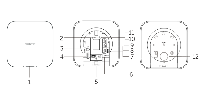
- LED indicator – multicolour status indicator that visually shows the status and modes of the device (see States and signalling).
- Power cable connector – for connection to the power supply.
- AP button – enters and exits access point mode:
- 4× press – enters access point (AP) mode for setting up the Hub.
- 1× press – exits access point (AP) mode.
- Tamper contact – switch protecting against sabotage and unauthorised manipulation of the device.
- Speaker – acoustically signals the states of the individual modes of the device at a volume of 70 dB.
- Reset button – pressing and holding the button for 3 seconds restarts the device and restores it to the default factory settings.
- Memory card slot – if an SD memory card is inserted in the device, event logs will be saved to it.
- SIM card slot 2 – serves as a backup communication channel.
- SIM card slot 1 – serves as the primary communication channel.
- Ethernet connector – for connecting a network cable with an RJ-45 connector.
- Power switch – used to switch the Hub on and off.
- Back cover / mounting bracket – serves as a protective cover and at the same time as a mounting bracket for fixed installation of the device.
Mobile operator SIM cards allow the Hub to use mobile data and communicate with the cloud and the FireSAFE mobile app.
If you install only one SIM card in the device, always use the SIM 1 slot for primary communication.
Even if two SIM cards are installed, the device can communicate through only one available channel at a time.
Communication through a SIM card will not be possible until the network connection configuration is completed.
In access point (AP) mode, the Hub broadcasts its own Wi-Fi network, to which the FireSAFE app connects, allowing you to set up the Hub's internet connection via this Wi-Fi connection.
Dimensions
Principle of operation
The SAFE 100HUB-WLRF Hub is the control element of the FireSAFE fire safety system. It can be linked wirelessly by pairing only with compatible wirelessly linkable FireSAFE elements. Once linked, the devices in the network can cooperate in exchanging data and pass it on to the user via the FireSAFE mobile app.
The Hub carefully monitors the operation of all connected devices and processes all data in encrypted form. In the event of an alarm, it immediately informs the user in the FireSAFE app about the events that have occurred and possible threats.
CONNECTED radio protocol
CONNECTED is a radio protocol designed for the FireSAFE wireless fire safety system. It uses the frequency band 868.0–868.6 MHz and allows communication between the individual elements of the system up to a distance of 1 000 m in open space without interference:
- two-way data transmission with integrity checking using the CRC8 method,
- if the radio signal is interfered with, the system alerts the user and automatically retunes to an interference-free frequency band,
- virus protection is handled at software level.
Protection against tampering and power failure
The Hub cannot simply be taken out of operation without the user's knowledge:
- it warns of device failure or loss of connection and saves this information to the event history,
- during a power outage it remains in operation powered by the backup battery,
- if radio communication is interfered with, it retunes to backup frequencies and notifies the user,
- if the Ethernet cable is interrupted, it continues communicating via another communication channel,
- on an attempt at sabotage or unauthorised manipulation, it triggers a tamper alarm via the Tamper contact.
Video verification and detection
In the event of an alarm, the Hub in the FireSAFE app provides the link between the individual sensors and the FireSAFE IP cameras. In addition to monitoring the observed area, these network IP cameras offer advanced functions such as flame detection, temperature measurement, video verification or intelligent warnings. Only cameras compatible with the FireSAFE app are supported.
Cloud firmware update
In addition to regular updates of the mobile app, the FireSAFE system also allows remote firmware updates of key devices, including the Hub. All updates take place via encrypted communication.
Capacity and linking
The Hub supports connecting up to 128 detectors, devices and other components of the FireSAFE CONNECTED ecosystem into one system – smoke alarms and heat alarms, carbon monoxide detectors, flammable and explosive gas detectors, environmental sensors and other elements. FireSAFE IP cameras can also be integrated into the system.
| Parameter | Value |
|---|---|
| Maximum number of linked devices | 128 FireSAFE units |
| IP camera support | Yes (only cameras compatible with the FireSAFE app) |
| Radio signal range | Up to 1,000 m in open space |
| Communication type | Two-way, automatic frequency hopping |
| System division | Devices can be arranged into rooms in the app; according to the product page, the system can be divided into up to 10 separate groups |
Power supply and backup
The Hub is mains powered 100–240 V AC, 50/60 Hz, 0.4 A with the supplied power cable. In case of a mains power failure, it is equipped with a built-in rechargeable 3.7 V / 4750 mAh (17.57 Wh) lithium battery with a standby time of up to 10 hours.
- When the mains power is disconnected, the Hub automatically switches to backup battery operation and continues monitoring the system.
- The battery is built in and is not user-replaceable.
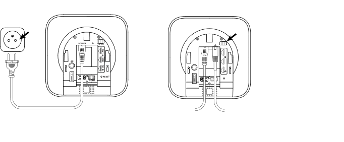
- Switch the Hub on and off using the power switch under the back cover.
- Connect the Hub only with the power cable supplied by the manufacturer and to a properly earthed socket.
Internet connection
To communicate with the cloud, the Hub uses a wired internet connection (Ethernet), a Wi-Fi network and a pair of SIM cards. It is recommended to use all communication channels to ensure a more reliable connection to the cloud even if one of the service providers fails; however, the device can also be operated on just one of the listed channels.
| Channel | Description |
|---|---|
| Ethernet (LAN) | A network cable with an RJ-45 connector plugs into the Hub's Ethernet connector. 10 Mb/s / 100 Mb/s port. An Ethernet cable is included in the package. |
| Wi-Fi | 2.4 GHz band only (IEEE 802.11b/g/n standard, 2400–2483.5 MHz, transmit power ≤ 20 dBm). Wi-Fi networks in the 5 GHz band are not supported. The Wi-Fi transmission range is 50 m. |
| Mobile network – SIM 1 | Primary mobile communication channel (2G / 3G / 4G). Insert the SIM card into the SIM 1 slot. |
| Mobile network – SIM 2 | Backup mobile communication channel. Only one SIM card is active at a time. |
Access point (AP) mode
Access point mode is used to set up the Wi-Fi connection. Pressing four times the AP button switches the Hub to this mode – the Hub broadcasts its own Wi-Fi network, to which the FireSAFE app connects and passes the login details for your network to the Hub. AP mode is indicated by the blue LED indicator flashing rapidly (once every 0.5 seconds). Press the AP button once to exit the mode.
SD memory card
An SD card can be inserted into the memory card slot, onto which the device's event logs will be saved locally. Use of an SD memory card is optional; the card is not supplied.
Adding to the FireSAFE app
The Hub is set up with the free mobile app FireSAFE for Android and iOS (including a Czech localisation). The app links all FireSAFE devices through a free cloud, which allows monitoring, setting and control of the system from anywhere in the world.
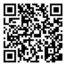
Before installing the Hub, make sure you have chosen the optimal location and that it meets the requirements given in this manual.
Make sure the Hub has a stable signal strength at all connected devices. If the signal strength is low, stable operation of the system is not guaranteed. In this case, take measures to improve the signal quality – for example, moving the Hub by just 20 cm can significantly improve signal reception.
If you have used the FireSAFE app before, check that you have the latest version installed. The minimum supported system versions are iOS 9.1 and Android 4.4.
Procedure for commissioning the Hub
- Connect your smartphone to a Wi-Fi network.
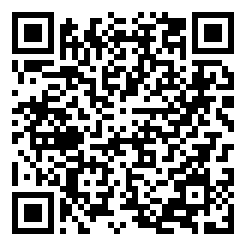
- Install the app on your phone FireSAFE from the App Store (for iOS) or Google Play (for Android), or download it by scanning one of the QR codes above.
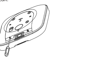
- Using a Phillips screwdriver, unscrew the locking screw securing the back cover.
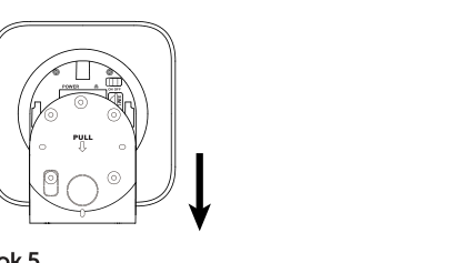
- Remove the back cover from the Hub by pushing it downwards. Take care not to damage the perforated part needed to activate the tamper contact if an attempt is made to tear the Hub off the surface.
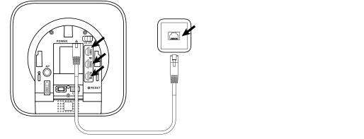
- Connect the individual communication channels to the Hub:
- with an Ethernet cable to the internet,
- via a Wi-Fi network to the internet,
- insert the mobile operator SIM card into the SIM 1 slot – primary communication,
- insert the mobile operator SIM card into the SIM 2 slot – backup communication,
- optionally insert an SD memory card.
- Connect the Hub to the power supply and switch it on by moving the power switch to the position ON.
- In the FireSAFE app, tap the button (+) to add a device, scan the QR code located on the back of the Hub and enter the information required by the setup wizard in the app.
- Fit the back cover onto the Hub and secure it again with the locking screw (for free-standing installation).
- Launch the app and carry out its basic setup.
- Confirm that the Hub has been added successfully in the FireSAFE app.
- Tap the button Save to confirm and save the configuration.
- Tap the assigned Hub to display information on network status, device status, signal strength, subordinate devices, alarm status and other information.
After a successful connection, the LED indicator lights up blue to indicate that a connection to the cloud has been established. The app then returns to the device name and room configuration page.
You can customise, rename and edit the names of the added devices and arrange the devices into the room where they are to be located.
Adding devices to the Hub
Alarms, detectors and other FireSAFE elements are added to the Hub by pairing from the FireSAFE app – by selecting Add device and then scanning the QR code on the bottom or back label of the device, or by entering it manually by selecting Enter manually. The app also offers the item Pairing detectors with the Hub.
States and signalling
The Hub signals its status visually with a multicolour LED indicator on the front and acoustically with a built-in speaker at a volume of up to 70 dB at a distance of 3 m.
| Status / mode | Signalling |
|---|---|
| Standby mode | The green LED indicator is continuously lit. |
| Pairing | The green LED indicator flashes rapidly (once every 0.5 seconds). |
| Exiting pairing mode | The LED indicator returns to standby mode, indicated by the green LED being continuously lit. |
| Alarm | The red LED indicator is lit. |
| Fault | The yellow LED indicator is lit. |
| Online | The blue LED indicator is lit – the device has established a connection to the cloud. |
| Access point (AP) mode | The blue LED indicator flashes rapidly (once every 0.5 seconds). |
| Reset | The red LED indicator flashes rapidly (once every 0.5 seconds). |
Voice warning messages
The SAFE 100HUB-WLRF Hub has a voice warning message system. In the event of danger, a fault or important changes in the network or system, the Hub informs the user about the current situation through various types of voice messages in the form of a human voice. The language of the voice warning messages is selectable and can be changed in the FireSAFE mobile app menu.
List of available voice warning messages
- Warning! Smoke has been detected!
- Warning! An abnormal temperature has been detected!
- Warning! Carbon monoxide has been detected!
- Warning! The smoke alarm has a fault!
- Warning! The heat alarm has a fault!
- Warning! The carbon monoxide alarm has a fault!
- Warning! The smoke alarm has a low battery!
- Warning! The heat alarm has a low battery!
- Warning! The carbon monoxide alarm has a low battery!
- Warning! The carbon monoxide alarm has reached the end of its life!
- Wi-Fi connection established successfully.
- Wi-Fi connection failed.
- The device is connected to the cloud.
- Connection to the cloud failed.
- Warning! The device has detected an alarm!
- Warning! The device is reporting a fault!
- Warning! The device is reporting a low battery!
- Warning! The device is reporting the end of its life!
Settings in the app
To open the Hub settings in the FireSAFE app, select the Hub in the device list and choose Device details. The following table summarises the items that the Hub offers in the app.
| Item | Meaning |
|---|---|
| Device name | Custom name of the Hub; shown in the device list and in notifications. |
| Room / Room management | Assignment of the Hub and connected devices to rooms; to create a new room, select Add room. |
| Status | Overview of the Hub's operating status: online/offline, signal strength, power status and backup battery, status of connected devices. |
| Signal strength | Level of the radio signal between the Hub and the connected devices. |
| Device Wi-Fi configuration | Connecting the Hub to a Wi-Fi network – options Select Wi-Fi, Wi-Fi name, Current Wi-Fi a Change Wi-Fi. Only the 2.4 GHz band is supported. |
| Volume | Setting the volume of acoustic signalling and voice warning messages. |
| Language | Language of the app and voice warning messages. |
| Firmware update | Display of the Hub's current firmware version and its remote update from the cloud. |
| Hub SN | Serial number of the Hub; it matches the information on the label with the QR code on the back of the device. |
| Share device / Sharing management | Sharing the Hub with other users and managing access that has already been shared. |
| Remove device | Removal of the Hub from the account in the app. |
Notifications and event history
The Hub informs the user about system events through notifications in the FireSAFE app, acoustic signalling and voice warning messages. Depending on the settings, alarm events can also be passed on by SMS or phone call to up to 5 phone numbers.
| Item | Meaning |
|---|---|
| Notifications | Push notifications about alarms, faults and other system events. |
| Message / Message details | Individual messages and their details, including the time of occurrence. |
| Alarm messages | Overview of the system's alarm events. |
| History search | Searching the system event history. |
Reset and troubleshooting
If the Hub indicates fault mode, proceed as follows:
- Restart the Hub – disconnect it from the power supply and connect it again.
- If the problem persists, perform a reset – restore the Hub to its default factory settings. Press and hold the button Reset for 3 seconds. The restore process is indicated by the rapidly flashing red LED indicator.
- If these steps have not helped, contact our technical support.
If the device is damaged or faulty, do not attempt any repairs yourself – contact your seller or our technical support.
Choosing the installation location
The Hub is intended for use in ordinary indoor spaces. Before mounting, choose a suitable installation location with an available connection to the power supply and the Ethernet network, and verify that the Hub has a stable signal strength at all connected devices.
Where not to install the Hub
- Near metal objects and structures that may weaken or block the radio signal.
- In places with a weak GSM mobile network signal.
- Near sources of radio interference – within 1 metre of a router and power cables.
- In places where temperature and humidity exceed the permitted limits.
- In places prone to vibration and shocks.
- In places exposed to direct sunlight, extreme cold or sudden changes in temperature.
- In damp, dusty or smoky spaces and in poorly ventilated places.
- Outdoors – the Hub is intended for indoor installation only.
Installing the Hub
The Hub's housing was designed so that it can be installed by simply placing it in the optimal position on a horizontal surface, or fixed to a wall with the supplied mounting material.
Wall mounting
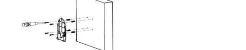
- At the installation location, use the back cover to mark and then drill holes with a diameter of 6 mm. Insert wall plugs into the prepared holes.
- Hold the back cover of the device against the wall and fix it with self-tapping screws; level the back cover before tightening the screws.
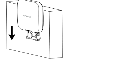
- Place the Hub with its back onto the back cover and slide it downwards so that it locks properly into the fixing position.
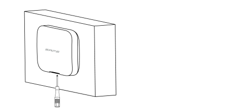
- Secure the Hub in the back cover with the locking screw.
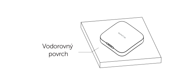
Free-standing installation on a horizontal surface
The Hub's housing design also offers the option of simply placing it on a horizontal surface. After placing it, make sure the device is stable.
Maintenance
To keep the device in good working order, follow the instructions and recommendations below:
- Do not place the Hub in places prone to vibration and shocks – they may damage it.
- Do not disassemble the Hub or interfere in any way with the device's internal electrical circuits. Any such attempt will result in loss of the warranty.
- Keep the Hub clean and protect it from moisture, dust and excessive temperature.
- Do not cover the Hub's ventilation openings and do not place any objects on it.
- Regularly check in the FireSAFE app the signal strength between the Hub and the connected devices and the status of the backup battery.
- If the Hub indicates fault mode, follow the chapter Reset and troubleshooting.
- Keep the Hub firmware up to date – updates are downloaded remotely from the cloud.
- If the device is damaged or faulty, do not attempt any repairs yourself and contact your seller or our technical support.
Technical specifications
| Model designation | |
| SAFE 100HUB-WLRF | FireSAFE smart Hub, white version |
| Order code | 100HUB-WLRF |
| Classification | Smart Hub |
| Capacity and interfaces | |
| Maximum number of linked devices | 128 FireSAFE units |
| IP camera support | Yes (only cameras compatible with the FireSAFE app) |
| Communication channels | Ethernet, Wi-Fi and mobile network (2G / 3G / 4G; supports installation of two SIM cards, only one SIM card can be active at a time) |
| Network port | 1× RJ-45, 10 Mb/s / 100 Mb/s |
| Memory card | SD card slot for local storage of event logs (card not supplied) |
| Audio output | 1 channel |
| Mobile app | FireSAFE – iOS 9.1 and higher; Android 4.4 and higher |
| Language localisation | Czech, Slovak, Polish, English, German |
| Functions | |
| LED indication | 1× multicolour status LED indicator |
| Buttons and controls | 1× power switch, 1× Reset button, 1× AP mode button |
| Built-in siren | ≤ 70 dB at a distance of 3 m |
| Signalling | Acoustic (siren up to 70 dB) and visual (LED indication) |
| Voice warning message system | Yes, language selectable in the app |
| Voice broadcasting | Phone or built-in speaker |
| SMS / phone call | Yes / yes (up to 5 phone numbers) |
| Tamper contact | Yes (Tamper) |
| Remote update | Yes (cloud) |
| Wireless transmission – CONNECTED | |
| Operating radio frequency | 868.0–868.6 MHz |
| Transmitter power (EIRP) | limit 25 mW |
| Communication type | Two-way |
| Communication range | Up to 1,000 m in open space |
| Data integrity check | CRC8 |
| Frequency hopping | Yes (automatic) |
| Wi-Fi and mobile network | |
| Wireless protocol | IEEE 802.11b/g/n |
| Wi-Fi frequency | 2.4 GHz (not compatible with 5 GHz Wi-Fi networks) |
| Wi-Fi frequency range | 2400–2483.5 MHz |
| Wi-Fi transmit power | ≤ 20 dBm @ 2400–2483.5 MHz |
| Wi-Fi transmission range | 50 m |
| LTE-FDD bands | B1 / B3 / B5 / B7 / B8 / B20 / B28 |
| General | |
| Power supply | 100–240 V AC, 50/60 Hz, 0.4 A |
| Backup battery | Rechargeable lithium 3.7 V / 4750 mAh (17.57 Wh); standby time up to 10 h |
| Operating temperature | −10 °C to +55 °C (+14 °F to +131 °F) |
| Operating humidity | Up to 95 % relative humidity, non-condensing |
| Storage conditions | Temperature: −10 °C to +55 °C; humidity: 10 % to 95 % relative humidity, non-condensing |
| Housing material | PC + ABS |
| Colour | White |
| Type of installation | Indoor |
| Mounting method | On a wall or on a horizontal surface (mounting material is included in the package) |
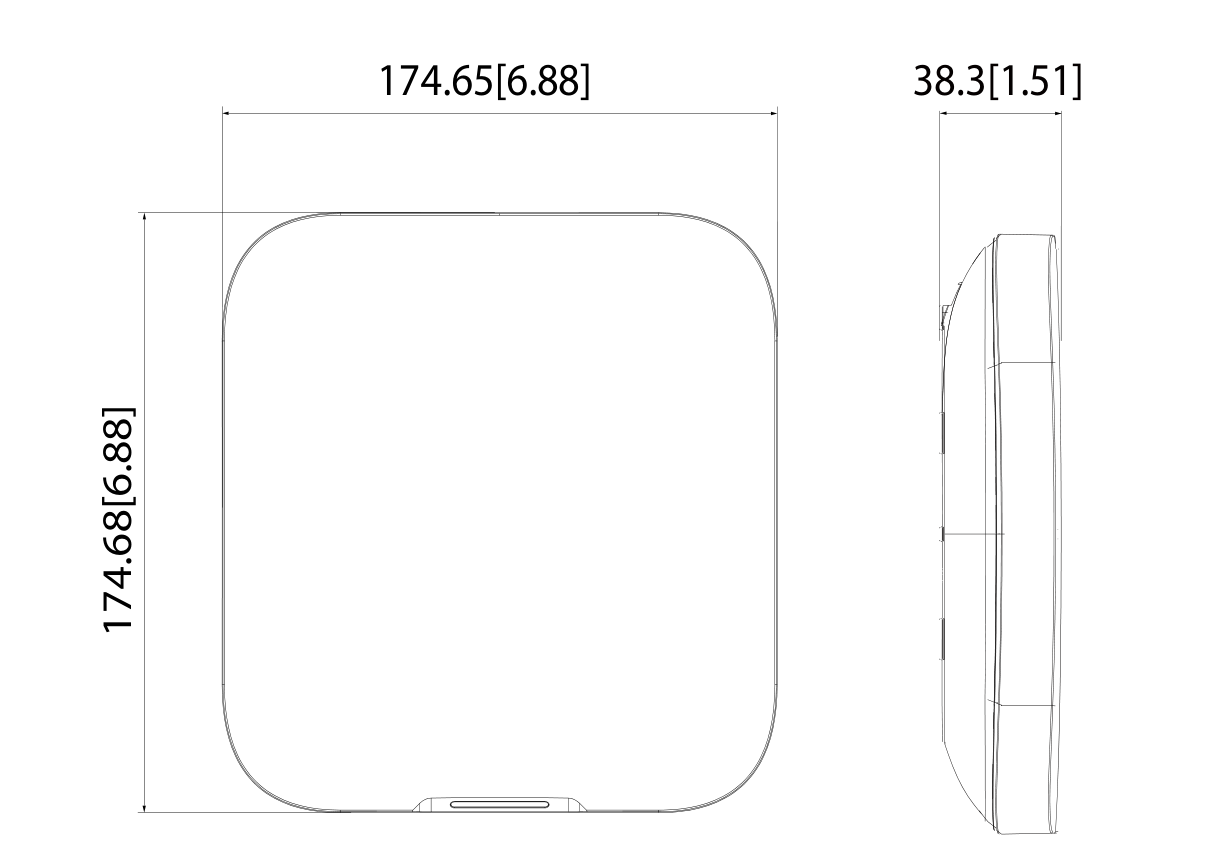
| Product dimensions | 174.8 × 174.8 × 38.3 mm |
| Product weight | 500 g |
| Declaration of Conformity | CE, UKCA |
| EAN code | 0728204234907 |
| Warranty | 36 months |
Package contents
Check the package contents against the following checklist. If you find that the device is damaged or the contents are incomplete, contact your seller.
- Hub SAFE 100HUB-WLRF – 1 pc
- Ethernet cable – 1 pc
- Power cable – 1 pc
- Self-tapping screws – 4 pcs
- Wall plugs – 4 pcs
- User manual – 1 pc
Safety notices
- Before use, check that the power supply is correct, and operate the Hub only within the rated range of the power input.
- Transport, use and store the Hub only within the permitted temperature and humidity range.
- Do not allow liquids to drip or splash onto the Hub, and do not place any objects containing liquid on it.
- Do not insert any objects into the ventilation openings of the product and do not cover the product.
- Strictly follow local electrical safety regulations and standards. The supply voltage must be stable and meet the requirements given on the device's label.
- Do not place the Hub in a location exposed to direct sunlight or near heat sources; keep it away from moisture, dust and soot.
- Place the Hub in a well-ventilated place and do not block its ventilation.
- Use only the power cable supplied by the manufacturer. Do not disconnect the power cable from the Hub while the device is connected to the mains.
- Connect Class I electrical appliances to a socket with protective earthing.
- The device contains a built-in rechargeable battery – do not throw it into a fire and do not crush or cut it mechanically.
- Do not disassemble the Hub and do not carry out any repairs on it yourself.
- The Hub is only a part of the fire safety system and does not replace the operator's fire protection obligations.
Disposal
Do not dispose of electrical appliances as unsorted municipal waste; use separate waste collection points. For current information on collection points, contact your local authorities. If electrical appliances are deposited in landfills, hazardous substances can leach into groundwater and enter the food chain, damaging your health.
Warranty
The SAFE 100HUB-WLRF Hub is covered by a warranty 36 months from the date of sale.
- The manufacturer warrants that the device will be free from any defects in material and workmanship under normal use and operation for a period of three years from the date of sale. The manufacturer's obligation under this warranty is limited to repairing or replacing the device or any part of it that it finds defective in material or workmanship, free of charge, after it is sent together with proof of the date of purchase and prepaid postage to the address of the service centre: SAFE HOME europe s.r.o., Čechova 1005/4, 750 02 Přerov, Czech Republic.
- This warranty becomes void if the product has been damaged, altered, misused or modified after purchase, or if it has stopped working as a result of poor maintenance or incorrect placement.
- Any implied warranties arising from this sale, including but not limited to implied warranties relating to description, merchantability and fitness for a particular purpose, are limited to the duration of this warranty.
- Under no circumstances shall the manufacturer or any of its parent or subsidiary companies, sales representatives or distributors be liable for loss of functionality of this product or for any indirect, special, incidental or consequential damage, or for costs or expenses incurred by the consumer or any other user of this product, whether on the grounds of breach of contract, negligence, strict liability in tort or otherwise.
- Neither the manufacturer nor any of its parent or subsidiary companies, sales representatives or distributors shall be liable for any injury to persons, damage to property or other special, collateral, incidental or consequential damage that may arise as a result of a gas leak, fire or explosion.
- This warranty does not affect your statutory rights.
Documents
- A declaration of conformity has been issued for the product.
- The individual declarations, the user manual and other documents for the product can be found at www.smart-safe.eu.
- Manufacture and service centre: SAFE HOME europe s.r.o., Čechova 1005/4, 750 02 Přerov, Czech Republic.
- Designed in the Czech Republic / made in the PRC.
Need help?
SAFE HOME europe technical support:
E-mail: info@safe-home.eu · Telephone: (+420) 581 222 262
Web: www.smart-safe.eu