
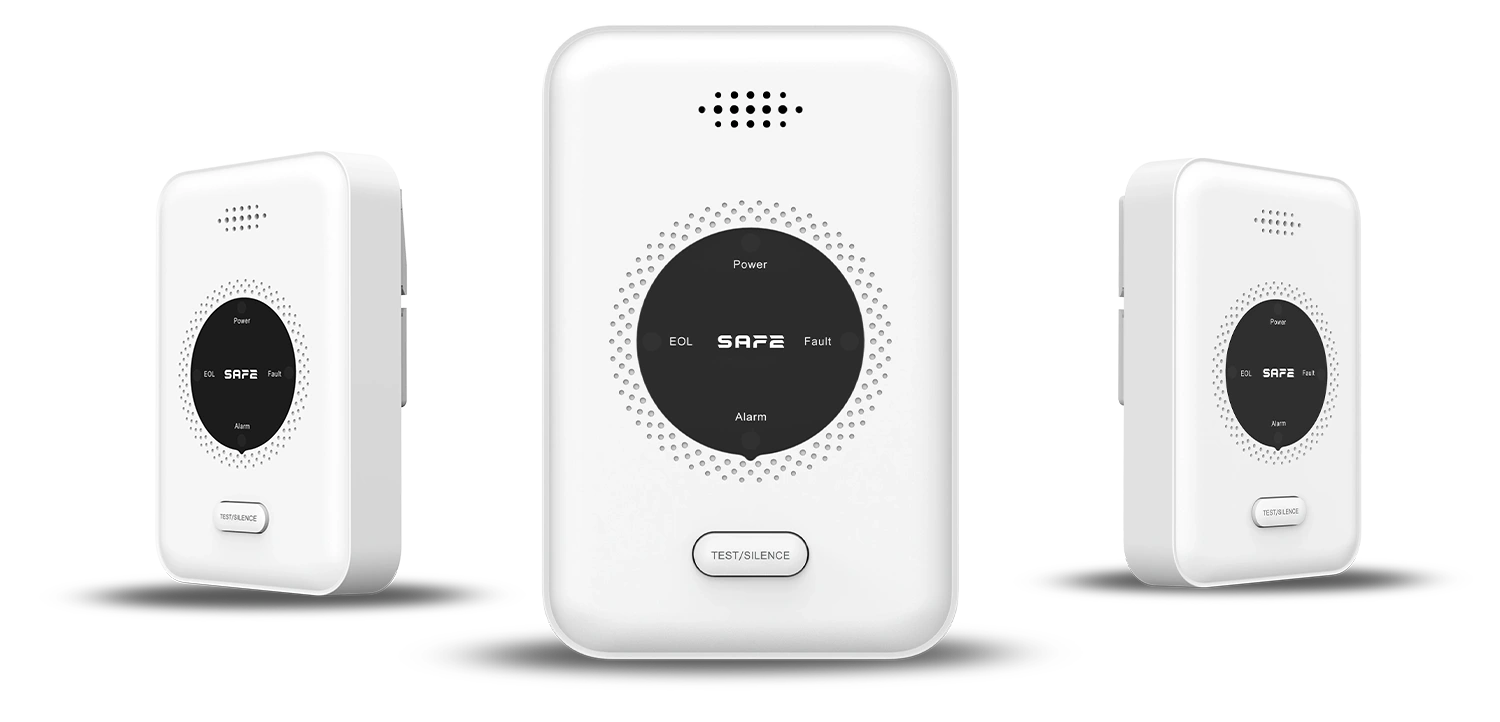
A new generation of wireless detector of flammable and explosive gases, designed to detect hazards from methane (CH4)-based gases such as natural gas, biogas, CNG, SNG, mine gas and the like. The detector's task is to provide timely warning of a threat in the event of a leak of flammable and explosive gases in the monitored area. The device is equipped with a relay output and a pulse output, which allows it to be easily integrated into third-party security and automation systems. The alarm can work as part of the FireSAFE fire safety system with the support of a FireSAFE Hub, or completely standalone. The SAFE 5YGAS-RF is powered by a safe voltage of 12 V DC through a 230 V / 50 Hz mains power supply included in the package.
Foreword
General
This user manual describes the installation, functions and operation of the wireless detector of methane-based flammable gases, CH4 (hereinafter the “detector”). Read the manual carefully before using the device and keep it for future reference. Study the manual regularly and go through the possible emergency procedures with all members of the household in case a gas alarm is triggered.
Safety instructions
The following signal words may appear in the user manual:
| Signal word | Meaning |
|---|---|
| NEBEZPEČÍ | Indicates a high potential hazard which, if not avoided, may result in death or serious injury. |
| VAROVÁNÍ | Indicates a medium or low potential hazard which, if not avoided, could result in minor or moderate injury. |
| UPOZORNĚNÍ | Indicates a potential risk which could lead to property damage, data loss, reduced performance or an unpredictable result. |
| TIP | Provides methods to help you solve a problem or save time. |
| POZNÁMKA | Provides additional information, such as emphasis or a supplement to the text. |
Revision history
| Version | Revision content | Release date |
|---|---|---|
| V1.0.0 | First release. | September 2026 |
| V1.0.1 | Colours according to the FireSAFE brand (red). | October 2026 |
About the manual
- The user manual serves as a reference only. Minor differences may occur between the information provided and the product.
- We are not liable for damage resulting from use of the product in a manner that is not in accordance with the instructions in the user manual.
- Printing errors or deviations may occur in the description of functions, operations and technical data. In case of doubt or dispute, we reserve the right of final interpretation.
- If you encounter any problems while using the device, visit our website or contact customer service.
Operating requirements
- Under no circumstances ignore the detector's alarm – such behaviour could lead to serious injury or death.
- Do not attempt to open or disassemble the detector – there is a risk of electric shock, failure or malfunction.
- Exposing the detector to high or low temperatures, or to high humidity, may significantly reduce the life of the device.
- Transport, use and store the device under the humidity and temperature conditions permitted by the manufacturer.
- Do not expose the device to frost, rain, water or damp, dripping or splashing water, and do not immerse it in water or other liquids.
- Do not insert any objects into the ventilation openings of the product, do not cover the product and prevent water or other liquid from entering.
- Do not place the device in locations prone to vibration and shock or near an open flame.
- The detector is intended only to indicate the presence of flammable gases based on methane CH4 – it does not detect smoke, flame, temperature or carbon monoxide.
- This product is intended for use in the normal indoor environment of single-family residential units.
- The detector requires a constant electrical power supply – without power it is not functional. The expected life of the device, with correct handling and maintenance, is 5 years.
- This device is not intended for use by persons with reduced physical, sensory or mental capabilities or a lack of experience and knowledge, unless they have been supervised or instructed in the use of the detector by a person responsible for their safety.
Installation requirements
- Incorrect installation and operation of this device will prevent it from functioning properly and, consequently, from responding to danger.
- When working at height, follow all safety procedures and use the required protective equipment.
- Do not expose the product to direct sunlight, extreme cold and damp or sudden changes in temperature – this would reduce the sensing accuracy of the sensor.
- Before using the device, you must stick information labels A and B in your language onto it (see chapter Installing the detector).
- Before using the device, make sure the detector is correctly connected to the power supply. Do not pull the power cable out of the device while the power adapter is plugged into the mains.
- Installation and handling of this device must always comply with local electrical safety requirements.
What to do in a gas alarm
If the detector senses a dangerous concentration of flammable gas, it triggers a loud alarm signal (85 dB) accompanied by visual indication from the red LED indicator. A gas alarm is indicated by continuous sounding of the buzzer's acoustic signal accompanied by a permanently lit red LED indicator. Press the TEST/SILENCE button to temporarily silence the alarm (for 9 minutes). If the dangerous gas concentration has not fallen during this time, the alarm is triggered again.
- Extinguish all open flames and all sources of ignition (heaters, cookers, pilot flames, cigarettes, etc.) and switch off all gas appliances.
- Do not use any electrical equipment, including a mobile phone or radio, and do not switch any electrical appliances on or off, including the detector itself.
- Shut off the gas supply and the main gas shut-off valve. Ventilate by creating a draught to disperse the gas – open windows and doors.
- Alert the people around you (do not ring neighbours' doorbells, only knock on their doors) and, if possible, leave the premises – leaks without combustion can create an explosive mixture.
- If the alarm is still active and the cause of the leak has not been found, leave the building and call the emergency number 112, the gas company on its emergency number, or the appliance service organisation.
Functional elements
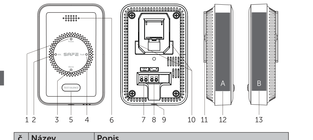
- Power LED indicator – green power LED indicator.
- EOL LED indicator – yellow end-of-life LED indicator.
- Alarm LED indicator – red LED indicator.
- Fault LED indicator – yellow fault LED indicator.
- TEST/SILENCE button – checks that the device is working and is used to temporarily silence the acoustic alarm signal.
- Buzzer – a small siren emitting an acoustic signal at 85 dB, indicating the states of the individual device modes.
- Relay – COM/NO relay output for connecting external wired devices.
- Valve – −/+ pulse voltage output for connecting external wired devices.
- Power input – 12 V DC / 1.0 A power connector.
- Slots – entry slots for placing the mounting bracket.
- Mounting bracket – for fixed installation on a wall.
- Label A position – place for sticking on information label A.
- Label B position – place for sticking on information label B.
Principle of operation
The SAFE 5YGAS-RF detector is designed for continuous monitoring, detection and signalling of gases whose main component is methane, CH4. It is suitable for residential and household spaces (kitchens, boiler rooms, workshops, garages, etc.) and indicates a leak of flammable gas such as natural gas. The device uses advanced second-generation semiconductor sensor, which does not require regular service calibrations, with a fast response, high sensitivity and high resistance to false alarms.
As soon as a concentration exceeding 8 % LFL/LEL, to which the sensor is calibrated, is detected, the device immediately triggers an acoustic and visual alarm signal. The detector includes an integrated RF module which, thanks to the function CONNECTED function, makes it possible to wirelessly link two or more FireSafe devices (maximum 24 units) and thus create an interlinked wireless network – see more in the chapter Interconnection. A FireSafe Hub can also be added to the network, which monitors the operation of all connected detectors and, if danger is detected, informs the user by means of an alarm in the mobile app.
The detector is type A and is certified to the European standard EN 50194-1:2023 for electrical apparatus for the detection of flammable gases in residential premises.
Two control outputs and integration into third-party systems
The detector has two control outputs – a relay output (COM/NO) and a pulse voltage output (−/+) – which allow direct connection and control of external devices such as automatic valves for shutting off the gas supply, alarm signalling elements or air-conditioning fans. Thanks to the COM/NO relay output, the detector can also be integrated into third-party security or automation systems: simply connect the detector to the integration module of the system concerned, which will receive the alarm signal through a wired input. For details, see chapter Connecting external devices.
Temporary alarm silencing
If necessary, the acoustic alarm signal can be temporarily silenced (for 9 minutes) by pressing the TEST/SILENCE button. The detector indicates temporary silencing mode with a permanently lit red LED indicator. If the gas concentration then falls below the set value, the detector automatically returns to normal operating mode.
Interconnection
The detector can be linked by pairing only with wirelessly linkable FireSafe devices. It is not intended for communication with wirelessly linkable devices of other brands or manufacturers. The interlinked network operates at a frequency of 868 MHz, with a range of up to 1 000 m in open space and support for up to 24 devices FireSafe CONNECTED. If one of the devices in the network raises an alarm, it transmits a radio signal and all other units connected to the network will respond to the alarm as well.
Before linking, make sure that all devices are armed and powered.
- Entering pairing mode – on the first device, press the TEST/SILENCE button briefly 4× in a row (interval between presses shorter than 1 second). The device emits a short acoustic tone and the LED indicator flashes red approximately once every 0.5 s to show that it has entered pairing mode (for 3 minutes).
- Connecting the second device – on the second device, press the TEST/SILENCE button briefly 2× in a row. The device emits a short tone and the red LED indicator flashes faster (approximately once every 0.25 s) to show transmission mode.
- Confirming pairing – after successful pairing, the second device emits a short sound signal and its LED indicator flashes green until the first device leaves pairing mode.
- Connecting further devices – while the first device is in pairing mode, repeat step 2 for each additional device. Using this procedure, up to 24 wireless FireSafe devices can be linked into the network.
- Checking functionality – once all the devices have been linked, test the whole wireless network (see chapter Function test and silencing).
Adding to the FireSafe app
A FireSafe Hub can be added to the wireless network of detectors – a key element of the system which, thanks to its internet connection, allows convenient setup and remote control using the free mobile app FireSafe (for both Android and iOS). The Hub monitors the operation of all connected detectors and, if danger is detected, immediately informs the user by means of an alarm in the app. If you connect to the Hub a device that is already part of a standalone wireless network, all devices of that network connect to the Hub at once.


Commissioning the FireSafe Hub
- Connect your smartphone to a Wi-Fi network and install the FireSafe app.
- Connect the FireSafe Hub to a power supply and to the internet (via an Ethernet cable or Wi-Fi).
- Launch the app and carry out the basic setup.
- In the app, tap the (+) button to add a device, scan the QR code on the back of the Hub and enter the required details.
- Confirm that the Hub has been added successfully and tap the Save button.
Pairing the detector with the Hub
- On the Hub, press the button three times in quick succession PAIRING – the Hub's LED indicator flashes green to show pairing mode.
- On the detector, press the TEST/SILENCE button briefly 3× in a row. The detector emits a short acoustic signal and the green LED indicator flashes approximately once every 0.25 s to show pairing.
- Once the device has been added successfully, the detector emits a short beep and the LED indicator flashes green slowly for one minute, then switches to normal operating mode.
- To add another detector, end the pairing mode of the device just paired by pressing the TEST/SILENCE button and repeat step 2. If the Hub's pairing interval (1 minute) expires, switch the Hub to pairing mode again.
Connecting external devices
The detector offers two control outputs for connecting external wired devices – the relay output Relay (COM/NO, 12 V DC, 1.5 A) and the pulse voltage output Valve (−/+, 12 V DC, 1.5 A). They are typically used to connect an automatic gas shut-off valve or to pass the alarm signal to the integration module of a third-party security system.
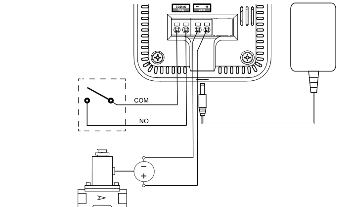
- Disconnect the detector from the power supply.
- Insert a thin flat screwdriver (or the end of a paper clip) into the opening above the input for the external device's wire and push on the contact.
- Insert the wire of the external device's cable into the input and release the tool.
- When the connection is finished, pull gently on the cable to verify that it is stable and firmly connected.
States and signalling
The detector indicates the individual operating states by a combination of four LED indicators (Power, EOL, alarm, Fault) and an acoustic buzzer:
| Status | Note | LED and siren |
|---|---|---|
| Start / end of initialisation or pairing mode | When plugged in / after initialisation is complete | All 4 LEDs lit for approx. 3 s, 1 beep |
| Detector initialisation | Approx. 180 seconds after plugging in | Green Power LED flashes, no sound |
| Standby mode | Normal operating mode of the device | Green Power LED lit steadily |
| Pairing mode with the Hub | 3× press of the TEST/SILENCE button | Green LED flashes (once every 0.5 s), 1 beep |
| Pairing mode between devices | 4× press of the TEST/SILENCE button | Red LED flashes (once every 0.5 s), 1 beep |
| Functionality test | Press of the TEST/SILENCE button in normal mode | All 4 LEDs flash 5× (2×), 5 beeps (2×) |
| Alarm indication | Gas detected | Red LED lit steadily, acoustic signal sounds continuously |
| Silencing the alarm | Press of the TEST/SILENCE button in alarm mode | Red LED lit steadily, no sound |
| Sensor fault | Replace the detector | Yellow Fault LED lit steadily, 1 beep |
| End of life | 5 years after commissioning – replace the detector | Yellow EOL LED flashes (once every 1 s), 1 beep |
| Detector switched off | Power cable disconnected from the mains | No signalling |
Choosing the installation location
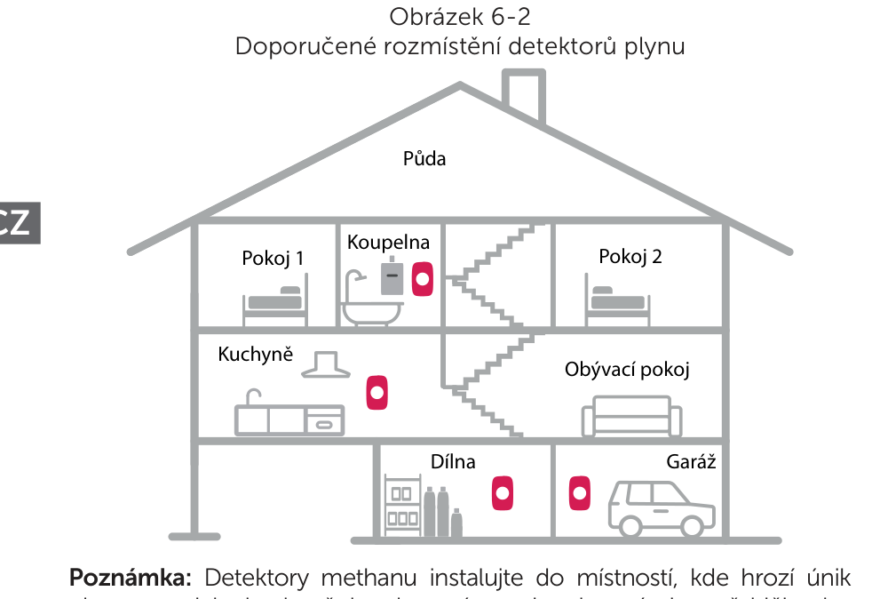
- The device must be installed by a competent person in accordance with the regulations in force. If in doubt, consult qualified professionals or contact our technical support.
- For the highest level of protection, gas detectors should always be installed in combination with smoke alarms, heat alarms and carbon monoxide (CO) detectors.
Physical properties of methane CH4
Methane (CH4) is a colourless, odourless, flammable gas (an odorant is added to natural gas for detection). It forms an explosive mixture with air. It is roughly half the weight of air and therefore rises to the ceiling when it leaks. In households, we encounter methane most often as a component of natural gas used for heating, cooking or water heating.
Detector location
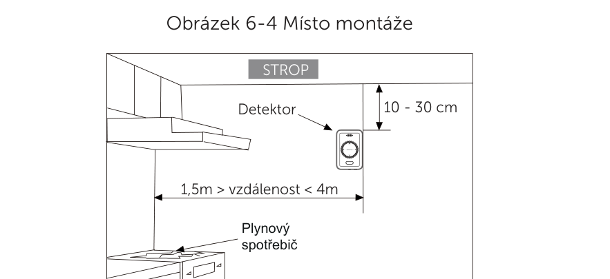
- The device is intended for wall installation in indoor spaces where the air temperature does not fall below −10 °C and does not exceed +55 °C at a relative humidity of up to 95%.
- Methane is lighter than air – install the detector approximately 10–30 cm from the ceiling and at a distance of 1,5–4 m from the potential source of the gas leak.
- The detector must be positioned higher than the highest point of an open window or door.
- Do not place the detector directly above an appliance or in close proximity to a heat source (e.g. above a cooker) – there is a risk of false alarms.
- Avoid places near windows, doors, fans or extractor hoods, where draughts or increased air circulation may reduce the gas concentration and delay detection.
- Mount the detector so that the alarm warning signal is clearly audible, especially in bedrooms and other living rooms.
- Take into account the length of the power supply cable (3 m) – it is not advisable to mount the detector farther away than the cable can reach the nearest socket.
Installing the detector
The SAFE 5YGAS-RF detector is designed for fixed installation on a wall using the supplied mounting bracket.
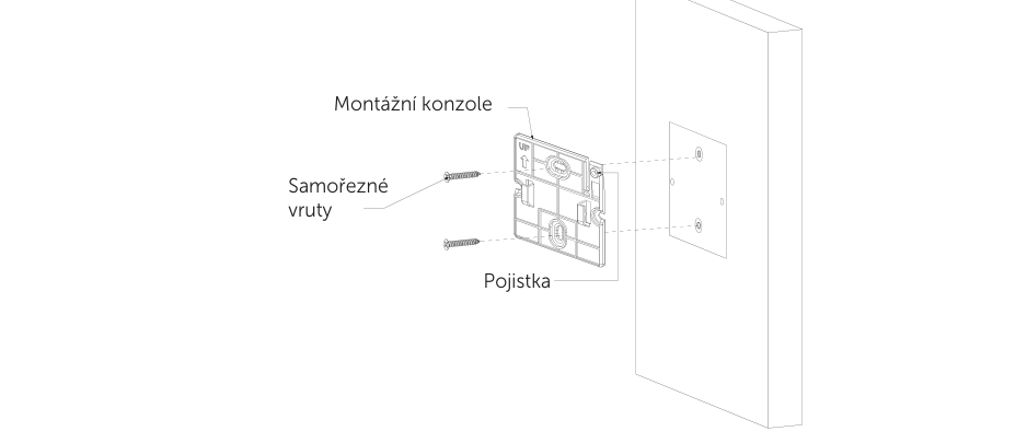
- Choose a suitable installation location according to chapter Choosing the installation location.
- Using the spacing of the mounting holes on the bracket, mark 2 points on the wall and drill the holes (⌀ 5 mm).
- Install wall plugs in the drilled holes and screw the mounting bracket to the wall with the supplied screws.
- From the set of information labels, stick labels A and B in the required language onto the device.
- Hang the detector by its entry slots on the mounting bracket and slide it on from top to bottom until the catch engages.
Commissioning and sensor warm-up
- Insert the power cable connector into the 12 V DC power connector input on the detector.
- Plug the power adapter into a 230 V mains socket.
- The siren beeps and all 4 LED indicators (Power, EOL, alarm, Fault) light up for 3 seconds.
- The green Power LED indicator then flashes regularly for 180 seconds, during which the sensor warms up and initialises – during this time the detector does not detect gas.
- Another siren beep then sounds and all 4 LED indicators light up again for 3 seconds to indicate that initialisation is complete.
- The green Power LED indicator on the device is lit steadily – the detector is ready to detect gas.
Function test and silencing
After installing the device or during its regular maintenance, a detector test must be carried out to prove that it is functional. We recommend carrying out a simulated alarm test at least once a week by pressing the TEST/SILENCE button.
To test devices linked in a wireless network, hold down the TEST/SILENCE button on any detector – the other connected detectors indicate receipt of the test signal with one short tone and a flash of the LED. To test devices connected via a Hub, select the detector in the FireSafe app and press the Test.
Press the TEST/SILENCE button to silence the acoustic alarm signal for 9 minutes – for a device linked in a network, this temporarily silences all devices except the detector that initiated the alarm (which can be silenced only by pressing the button directly on it).
Maintenance
- Carry out a simulated gas alarm test at least once a week by pressing the TEST/SILENCE button.
- Use a slightly damp soft cloth for cleaning. Do not use solvents or cleaning agents – they could scratch the plastic parts and damage the electrical circuits.
- The detector should be cleaned at least once a month. First disconnect it from the power supply and remove it from the mounting bracket, remove dust particles from the openings around the perimeter with a vacuum cleaner, then reinstall it, connect the power and, once initialisation is complete, test it with the TEST/SILENCE button.
- Do not use air fresheners, hairsprays, paints or other aerosols near the detector – silicone vapours, hydrogen sulphide, sulphur oxides, chlorine gas, hydrogen chloride, alkali metals, hydrogen, alcohol, isobutane, isopropanol, ethylene, ethyl acetate, benzene, toluene, thinners, solvents, adhesives and some cleaning agents may cause a false alarm or damage the sensor.
- Do not paint the device – paint could seal the grille openings and impair the function of the sensor.
- The detector cannot be disassembled. Opening the device automatically voids the warranty.
Troubleshooting common problems
| Problem | Possible solution |
|---|---|
| The green Power LED indicator does not flash / is not lit | Check that the power cable is connected correctly; it may be an LED fault – contact technical support |
| The detector does not sound the acoustic signal during testing | Wait for the device initialisation to finish (approx. 180 s) and make sure you pressed the TEST/SILENCE button correctly |
| No reaction to detected methane | The device does not start detecting gas until initialisation (sensor warm-up) is complete |
| The device emits a high, continuous acoustic signal | A large amount of volatile substances (alcohol, perfume, petrol) may be present in the area – move the device to clean air and leave it for 2 hours to decontaminate the sensor |
End of life
The expected life of the sensor and the device, with correct handling and maintenance, is min. 5 years from commissioning. The detector indicates an approaching end of life by flashing the yellow EOL LED indicator (once every 1 s) accompanied by a regular beep of the buzzer for 30 days before operation ends permanently. When the device signals end of life, it is no longer able to detect gas and must be replaced immediately with a new one. The replacement date is given on information label A. If you use several detectors, check the replacement date on all of them.
Technical specifications
| Detection parameters | |
| Detection type | Methane CH4 / natural gas |
| Sensor | Semiconductor sensor, 2nd generation |
| Device type | A |
| Alarm threshold | 8 % LFL (LEL) |
| Sensor warm-up time | 180 s (every time it is connected to power) |
| Detection certification | ČSN EN 50194-1:2023 |
| Wireless linking | |
| Operating frequency | 868 MHz |
| Signal range | Up to 1,000 m in open space |
| Max. number of linked devices | 24 units of the FireSafe CONNECTED type |
| Interfaces and functions | |
| Indication | 4× LED indicator (Power, EOL, alarm, Fault) |
| Controls | 1× TEST / SILENCE button |
| Alarm signalling | Acoustic (>85 dB at a distance of 1 m) and visual (red LED) |
| Silencing the alarm | Manually by button, for 9 minutes |
| Relay output | 1× COM/NO (12 V DC, 1.5 A) |
| Pulse voltage output | 1× −/+ (12 V DC, 1.5 A) |
| Power supply | |
| Power adapter | 100–240 V ~ 50/60 Hz (max. 0.3 A) |
| Detector | 12 V DC / 1.0 A (12.0 W), cable length 3 m |
| Power consumption | Standby mode ≤ 1.5 W; in alarm ≤ 2.5 W |
| General | |
| PCB protection | IZOVAX insulating and protective varnish layer with nanoparticles |
| Mounting method | Wall-mounted – fixed installation (screws included in the package) |
| Type of installation | Indoor – fixed installation |
| Degree of protection | IPX2D |
| Housing material / colour | PC + ABS, white / black |
| Operating temperature | −10 °C to +55 °C |
| Operating humidity | 10–95 % relative humidity, non-condensing |
| Storage temperature | −20 °C to +60 °C |
| Storage humidity | 5–95 % relative humidity, non-condensing |
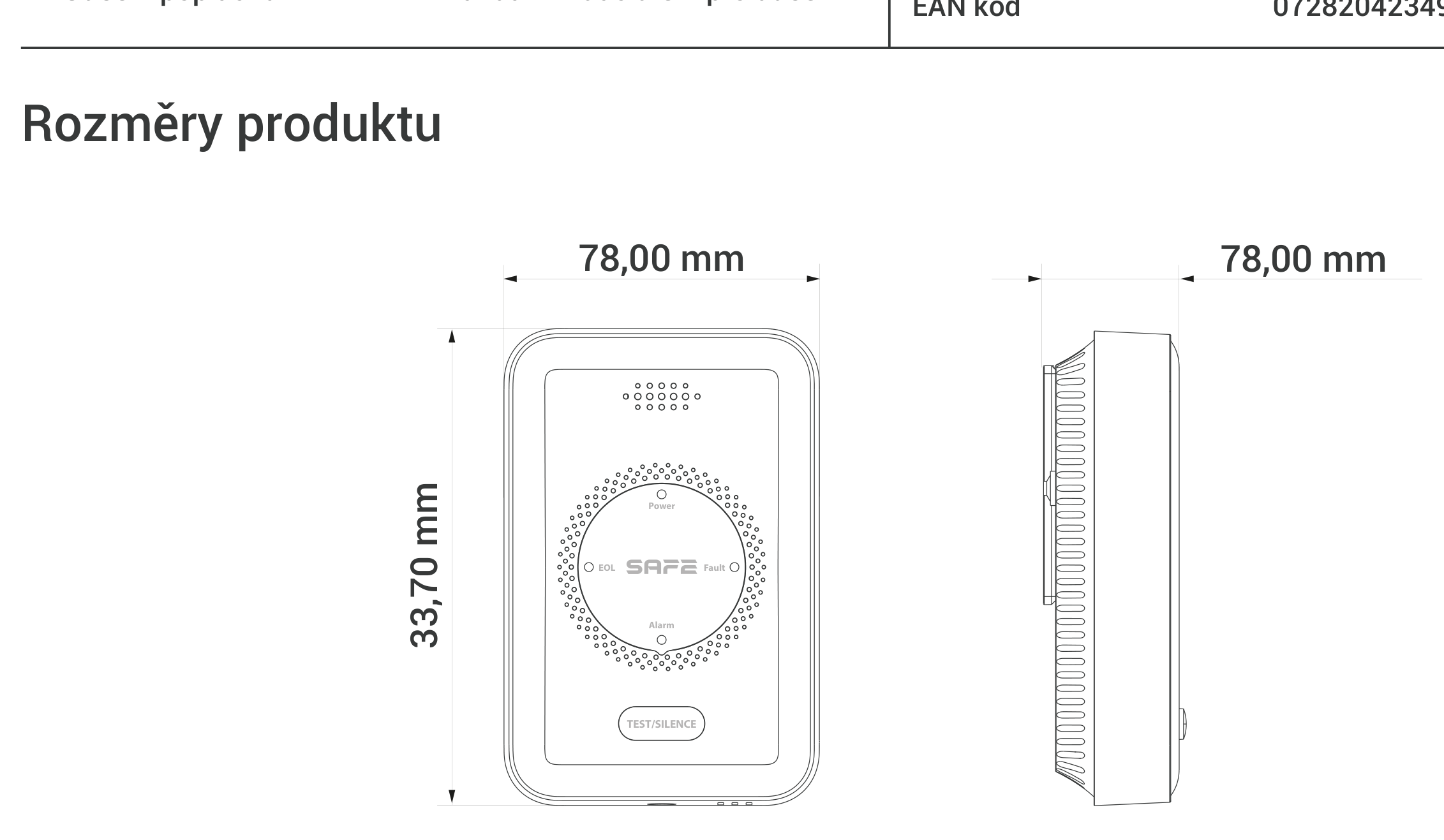
| Dimensions | 118.0 × 78.0 × 33.7 mm |
| Weight | 126 g (232 g with power adapter) |
| Package dimensions / weight | 78 × 90 × 135 mm, 321.6 g |
| Carton | 903 × 800 × 580 mm, 30 pcs, 10.4 kg |
| Sensor life | min. 5 years |
| Declaration of Conformity | CE |
| EAN | 0728204234914 |
| Warranty | 36 months |
Package contents
- Wireless gas detector SAFE 5YGAS-RF – 1 pc
- Power adapter with power cable – 1 pc
- Self-tapping screw – 2 pcs
- Wall plugs – 2 pcs
- Mounting bracket – 1 pc
- User manual with a set of information labels – 1 pc
Safety notices
- Read these instructions carefully before use and keep them for future reference and for any subsequent user.
- Under no circumstances ignore the detector's alarm signalling – such behaviour could lead to serious injury or death.
- Do not attempt to open or disassemble the detector – there is a risk of electric shock, failure or malfunction of the device; by opening the device you automatically lose the warranty.
- The detector requires a constant electrical power supply – without power it is not functional and does not protect against gas leaks.
- Transport, use and store the device only in the humidity and temperature conditions permitted by the manufacturer. Do not expose it to water, moisture, frost, or dripping or splashing water.
- Do not insert any objects into the ventilation openings, do not cover the device and prevent water or other liquids from entering.
- The detector is intended only to indicate the presence of flammable gases based on methane CH4 – it does not detect smoke, flame, temperature or carbon monoxide.
- The device is not intended for use by persons with reduced physical, sensory or mental capabilities, or by persons lacking sufficient experience and knowledge, unless they are supervised or have been instructed by a person responsible for their safety. Children must be supervised to ensure that they do not play with the device.
- This device must be installed by a competent person in accordance with the manufacturer's instructions and national regulations for the installation of gas appliances and shut-off valves.
- Installing this detector does not replace the correct installation, use and maintenance of fuel-burning appliances, including adequate ventilation and exhaust systems.
- Do not dispose of the product with general municipal waste or burn it – hand it in for recycling in the electrical equipment take-back system.
Warranty
The manufacturer provides a warranty on the SAFE 5YGAS-RF detector 36 months from the date of sale. The manufacturer's obligation under this warranty is limited to repairing or replacing the detector or its defective part, after the device has been sent together with proof of purchase to the address of the SAFE HOME europe s.r.o. service centre, Čechova 1005/4, 750 02 Přerov.
The warranty does not cover defects caused by failure to follow the instructions in this manual, or by damage, modification or misuse of the product. This warranty does not affect your statutory rights.
In case of problems with the device, first contact technical support – most situations can be resolved remotely.
Need help?
SAFE HOME europe technical support:
E-mail: info@safe-home.eu · Telephone: (+420) 581 222 262
Web: www.smart-safe.eu