
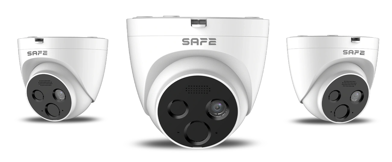
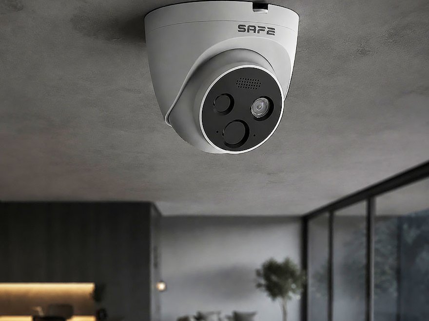
Turret Cam AI is a versatile network IP camera combining fire protection, security, video verification and surveillance of the monitored area. It has two sensors – visible and thermal – and a range of advanced functions such as flame and temperature detection, intercom, intelligent visual and acoustic warning, and IR night-vision illumination. Each sensor transmits video as a separate channel.
Foreword
General
This user manual describes the installation, functions and operation of the network fire camera (hereinafter the “camera”). Read the manual carefully before using the device and keep it for future reference.
Safety instructions
The following signal words may appear in the user manual:
| Signal word | Meaning |
|---|---|
| NEBEZPEČÍ | Indicates a high potential hazard which, if not avoided, may result in death or serious injury. |
| VAROVÁNÍ | Indicates a medium or low potential hazard which, if not avoided, could result in minor or moderate injury. |
| UPOZORNĚNÍ | Indicates a potential risk which could lead to property damage, data loss, reduced performance or an unpredictable result. |
| TIP | Provides methods to help you solve a problem or save time. |
| POZNÁMKA | Provides additional information, such as emphasis or a supplement to the text. |
Revision history
| Version | Revision content | Release date |
|---|---|---|
| V1.0.0 | First release. | September 2026 |
| V1.0.1 | Technical specifications corrected according to the manufacturer's documents. | October 2026 |
| V1.0.2 | Photo gallery added. | October 2026 |
| V1.0.3 | Text changes: Camera installation, Camera installation (drawing). | November 2026 |
Privacy notice
As a user of the device or a data controller, you may collect the personal data of others, such as their face, fingerprints and licence plate number. You must comply with local privacy protection laws and regulations in order to protect the legitimate rights and interests of other people by taking measures which include, but are not limited to: providing clear and visible identification to inform people of the existence of the monitored area and providing the required contact information.
About the manual
- The user manual serves as a reference only. Minor differences may occur between the information provided and the product.
- We are not liable for damage resulting from use of the product in a manner that is not in accordance with the instructions in the user manual.
- The manual will be updated in line with the current laws and regulations of the relevant countries. For detailed information, see the printed user manual, scan the QR code or visit our website. The manual is for information purposes only. The electronic and printed versions may differ in minor details.
- All designs and software may be changed without prior written notice. As a result of product updates, certain differences may appear between the product and the information in the manual. The latest version of the software and supplementary documentation is available from customer service.
- Printing errors or deviations may occur in the description of functions, operations and technical data. In case of doubt or dispute, we reserve the right of final interpretation. If the manual (in PDF format) cannot be opened, update your reader software or try another common reader.
- All trademarks, registered trademarks and company names in the manual are the property of their respective owners.
- If any problems occur while using the device, visit our website, or contact your supplier or customer service.
- In case of ambiguity or dispute, we reserve the right of final interpretation.
Important precautions and warnings
This section contains information on the correct handling of the product, risk prevention and prevention of property damage. Read it carefully before using the device and follow the instructions provided while using it.
Electrical safety
- All installation and operation must comply with local electrical safety regulations.
- The power supply must meet the requirements of the SELV (Safety Extra Low Voltage) standard and supply the device with a rated voltage that meets the power source requirements of the IEC 60950-1 standard. The power supply requirement is governed by the device label.
- Before starting the device, make sure that the power supply is correct.
- An easily accessible disconnecting device must be built into the building's installation wiring.
- Prevent damage to the power cable, especially the plug, socket and connections leading from the device.
- Do not provide two or more power sources for the device at the same time – this could damage it.
Environmental requirements
- Do not aim strong light, such as lamp light or sunlight, at the device – this could cause excessive brightness or light streaks, which are not a device fault and shorten the life of the CMOS sensor.
- Do not place the device in a damp or dusty environment, at extremely high or low temperatures, in places with strong electromagnetic radiation or in places with unstable lighting.
- Keep the device away from liquids to prevent damage to internal components.
- Ensure good ventilation to prevent heat from accumulating.
- Transport, use and store the device within the permitted humidity and temperature range.
- During transport, storage and installation, heavy stress, violent vibration and splashing water are not permitted.
- Install the device in a location accessible only to qualified personnel with knowledge of safety precautions and warnings.
Installation requirements
- It is recommended to use the device together with lightning protection.
- To increase reliability, it is recommended to earth the device.
- Use standard components or accessories supplied by the manufacturer and make sure that the device is installed and maintained by qualified technicians.
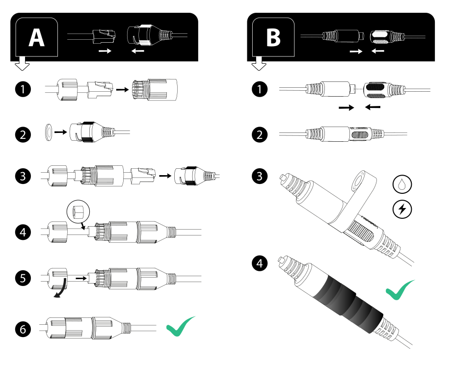
- Seal all cable connections watertight with insulating tape and waterproof tape to prevent short circuits and water damage.
- The surface of the image sensor must not be exposed to laser beam radiation in an environment where a laser-beam device is used.
- Strengthen the protection of your network, device data and personal data – use a strong password, change it regularly, update the firmware to the latest version and segregate your computer network. On devices with an older firmware version, the ONVIF password does not change automatically together with the system password; you must update the firmware or change the ONVIF password manually.
Functional elements and cables
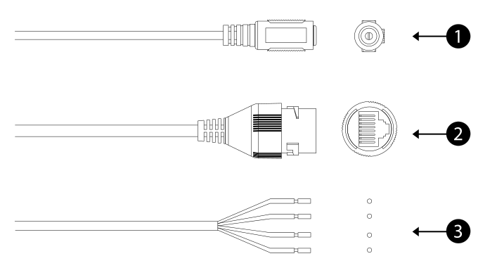
- Power supply – 12 V DC input. Make sure that the power supply complies with the instructions in this manual.
- LAN – connection to the network via a network cable; it also powers the camera via PoE.
- Alarm inputs and outputs – input and output port for alarm signals (see Alarm input and output).
Principle of operation
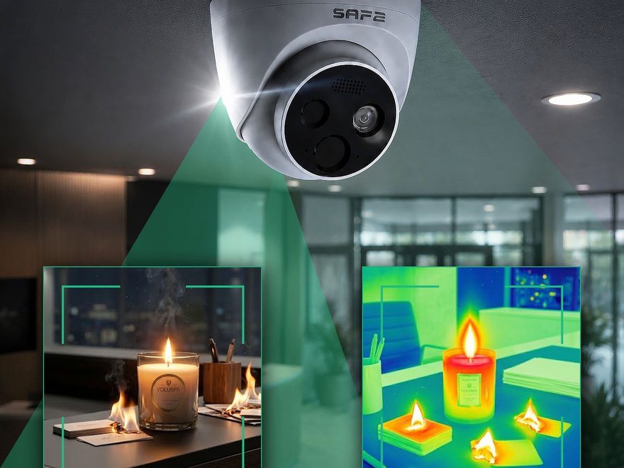
The Turret Cam AI is a dual-channel network camera. The visible sensor captures a normal high-resolution image, while the thermal sensor measures the temperature distribution of the scene and detects flame. The camera transmits both images as separate video channels – so it occupies two positions in the recording device.
Visible sensor
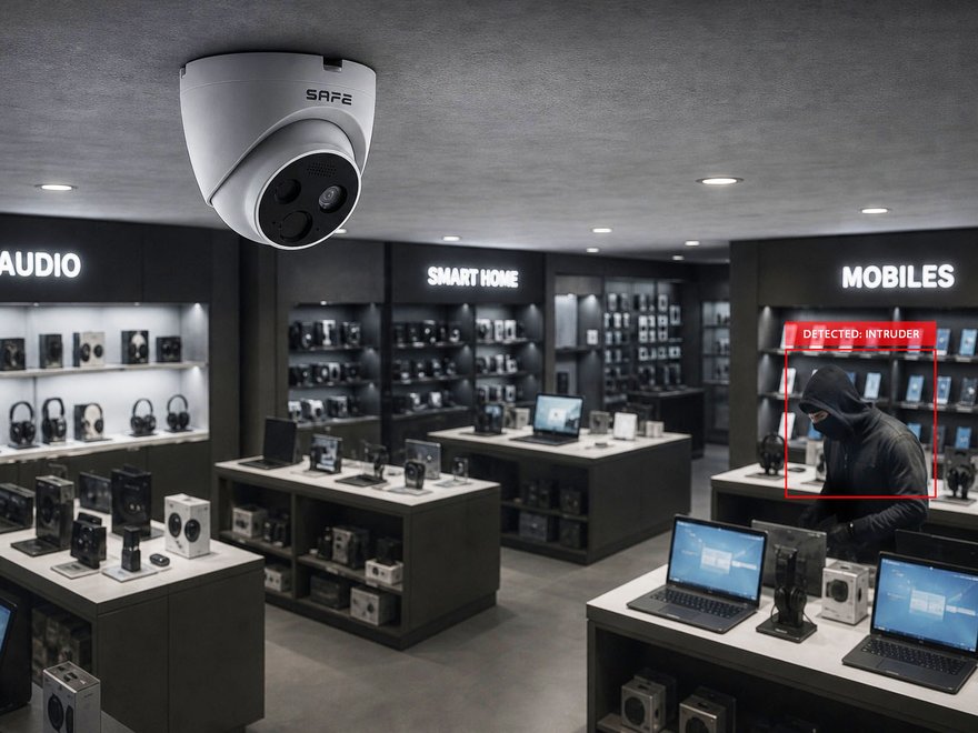
1/2.7" CMOS sensor with a resolution of 4 Mpx (up to 2688 × 1520 px at 25 fps) and a fixed 4 mm focal length lens covers a field of view of H 85°, V 44°, D 99°. It is used for general surveillance – monitoring the movement of people, animals or vehicles in real time – and for video verification of alarm events.
In the dark, it automatically switches on adaptive infrared illumination (1 IR LED, range up to 15 m) and the image switches to black-and-white mode (ICR). Scenes with high contrast are balanced by the DWDR, and noise is suppressed by two-stage 2D NR and 3D NR reduction.
Thermal sensor
An uncooled VOx detector with an effective resolution of 120 × 90 px and a spectral range of 8–14 µm captures the infrared radiation emitted by objects and converts it into a visual image. The field of view is H 90°, V 67.5°.
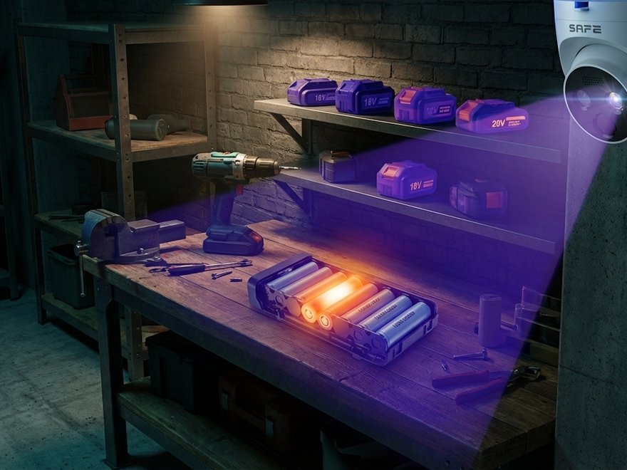
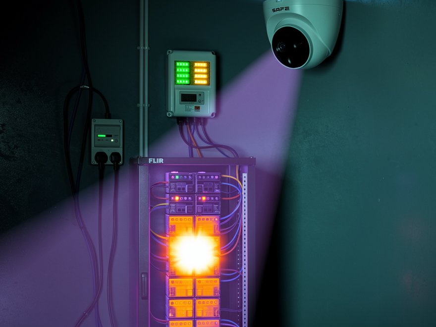
The thermal image works independently of lighting – it is useful at night, in dense fog or in smoke. It makes it possible to monitor temperature anomalies that cannot be seen by the naked eye or by the visible sensor: overheating equipment, batteries, heat leaks or an incipient fire.
Flame detection
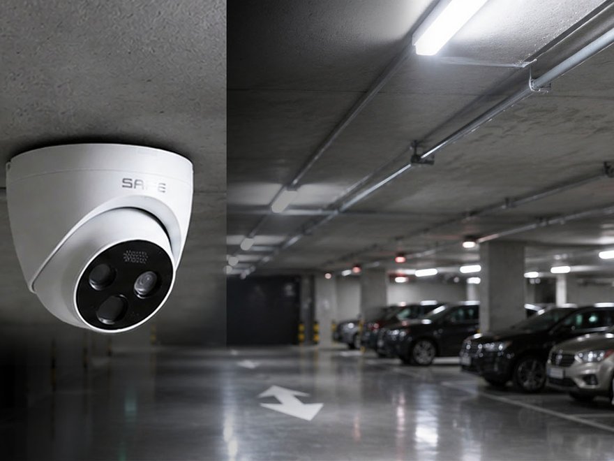
The camera detects and tracks a flame measuring 10 × 10 cm at a distance of up to 10 m. It is suitable for areas where a fire needs to be located quickly – garages, warehouses, technical rooms, areas with battery storage or charging of electric vehicles and two-wheeled vehicles.
Temperature measurement
The thermal sensor measures temperature in the range −10 °C to +200 °C with an accuracy of max. ±5 °C or ±5 %. It supports four modes:
- real-time spot temperature measurement,
- three simultaneous measurement rules – points, lines or polygons,
- temperature alarm when a set limit is exceeded,
- cold-spot and hot-spot alarm.
Intercom and voice warning
The built-in microphone and speaker allow two-way voice communication with the monitored area directly from the FireSAFE app. The camera also has a voice message – it informs of the situation with a human voice in the event of danger, a fault or a change in network status.
Where the camera is used
The camera can operate completely autonomously, as part of a fire system in the FireSAFE app. The procedure is described in the chapter Adding to the system.
Alarm input and output
The camera can be connected via a digital input and output to an external alarm device – for example a combustible gas detector, a PIR sensor, a magnetic door contact, a siren or a beacon light.
Input
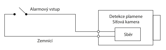
Connect the input device to the alarm input end of the I/O port. The camera senses the input state as follows:
- logic “1” – the input signal is connected to +3 V to +5 V, or is idle,
- logic “0” – the input signal is grounded.
Then, in the web interface, set the input mode to NO (default) if the signal is logic “0”, or to NC, if the signal is logic “1”.
Output
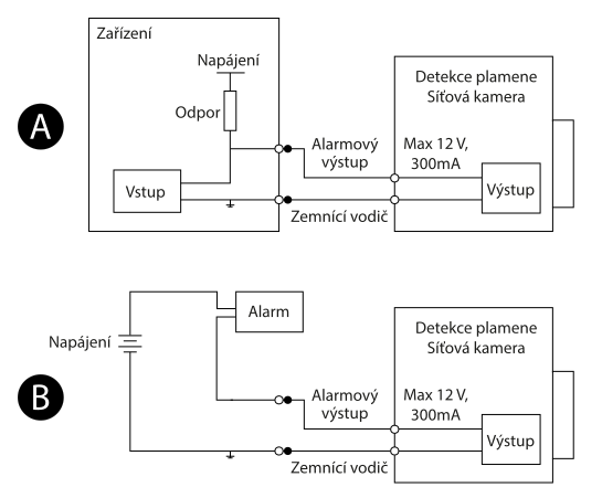
| Mode | Description |
|---|---|
| A – level | The output is of the OD type and requires an external pull-up resistor to function (typically 10 kΩ). The maximum external pull-up level is 12 V and the maximum port current is 300 mA. The default output signal is a high level; during an alarm it switches to low (at a current below 300 mA, the low-level voltage is below 0.8 V). |
| B – switching | The output drives an external circuit. The maximum voltage is 12 V and the maximum current is 300 mA. For a higher voltage, use an additional electrical relay. |
Both the alarm input and output are configured in the camera's web interface in the alarm settings.
Network configuration
Device initialisation and IP address setup can be completed using the ConfigTool or directly in the camera's web interface.
Device initialisation
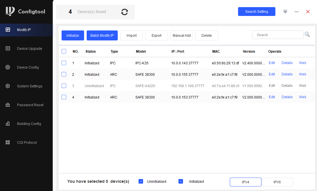
- Launch ConfigTool position and tap Modify IP.
- Tap Search setting, enter the start and end IP address of the network segment in which you want to search for devices, and confirm with OK. A list of discovered devices is displayed.
- Select a device with the status Uninitialized position and tap Initialize.
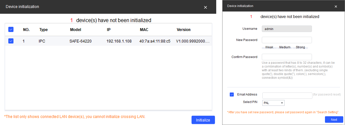
- Set and confirm the device password and enter a valid e-mail address for possible password recovery. Tap Next.
- Select the options according to your needs and confirm with OK. When finished, the device status changes to Initialized.
' " ; : &.IP address modification
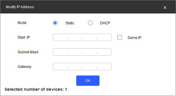
- Search for the device in the same way as during initialisation, select it and tap Modify IP.
- Select Static and enter the IP address, subnet mask and gateway. When you select DHCP the camera obtains its address automatically from the DHCP server on the network.
- Confirm OK.
Logging in to the web interface
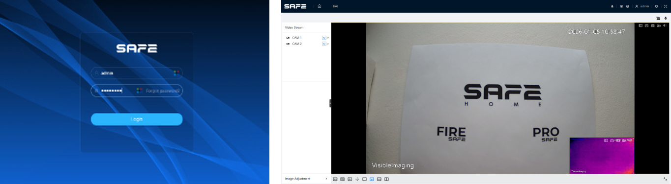
- Open a browser, enter the camera's IP address in the address bar and press Enter. If the setup wizard appears, complete it by following the instructions.
- Enter your username and password and tap Log in.
- On first login, click Click here to download plugin and install it by following the instructions. The main interface is displayed once installation is complete.
Adding to the system
In the app, the camera behaves as a separate device, where each image (visible and thermal) is a separate video channel – the camera therefore occupies two positions on the recording device.
FireSAFE – fire safety system
FireSAFE is a specialised fire safety app for use with devices of the FireSAFE system, such as the 10Y30 - RF smoke alarm or the 10YDCO - RF carbon monoxide detector.
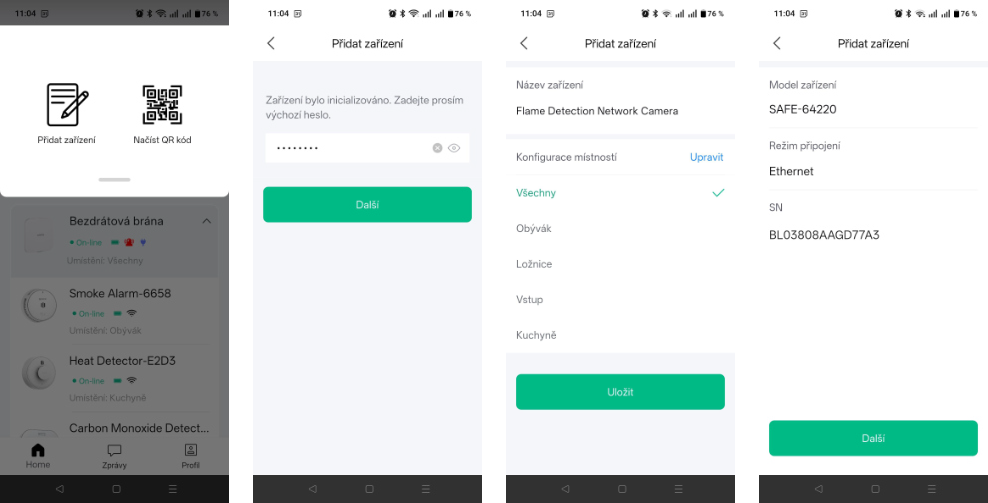
- Download and install the app FireSAFE from Google Play or the App Store (smart-safe.eu/firesafe/app).
- After launching the app, register and create an account by following the instructions.
- Tap +, scan the device QR code and enter the password set during initialisation.
This adds the camera to the system as a visual flame and temperature detector.
Detection settings
Detection limits, detection types (temperature, flame, motion) and detection zones are set in the camera's web interface at its IP address, in the menu Event (or Event). The FireSAFE app does not set these parameters.
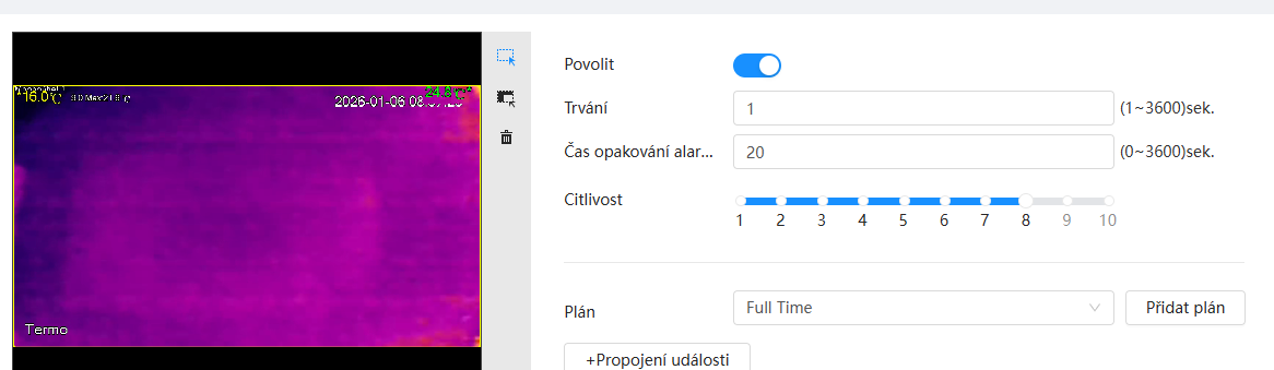
| Settings | Value |
|---|---|
| Enable | Switches the detection rule on |
| Duration | How long the condition must last for an alarm to be raised (0–3,600 s) |
| Repeat time | Shortest time before the same alarm is raised again (0–3,600 s) |
| Sensitivity | Sensitivity level of the rule (1–10) |
| Schedule | Time schedule when the rule is active (continuous by default) |
| Event linkage | Response to an alarm – alarm output, email, snapshot, recording |
| Detection zones | Points, lines or polygons in which the temperature is evaluated |
| Temperature unit | Degrees Celsius or Fahrenheit |
| Privacy masking | Up to 4 areas excluded from both recording and preview |
Visual and acoustic warning
When flame is detected, the camera triggers a visual and audible warning. Both can be switched on or off independently in the settings. The built-in speaker plays voice messages in a human voice – informing about danger, faults and changes in network or system status.
Choosing the installation location
Position the camera so that it has a direct, unobstructed view. Both flame detection and temperature measurement work optically – anything between the camera and the monitored location (a pillar, shelf, tarpaulin, glass) will prevent detection.
- The recommended distance for both temperature and flame detection is up to 10 m.
- The minimum focusing distance of the visible sensor is 1 m, of the thermal sensor 0.5 m.
- The infrared illumination range is up to 15 m.
Where not to install the camera
- Facing strong light – a lamp, floodlight or direct sunlight.
- Behind glass or another transparent barrier – the thermal sensor does not measure through glass.
- In places with strong electromagnetic radiation or unstable lighting.
- In areas with restricted air flow, where heat would build up.
- Outside the permitted temperature and humidity range (−10 °C to +55 °C, up to 95 % RH non-condensing).
Camera installation
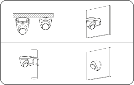
The camera is mounted on a ceiling or a wall. The cabling can be routed either through a hole in the mounting surface, or a side cable outlet. The tool required for installation, such as an electric drill, is not included in the package.
Cabling through a hole in the mounting surface
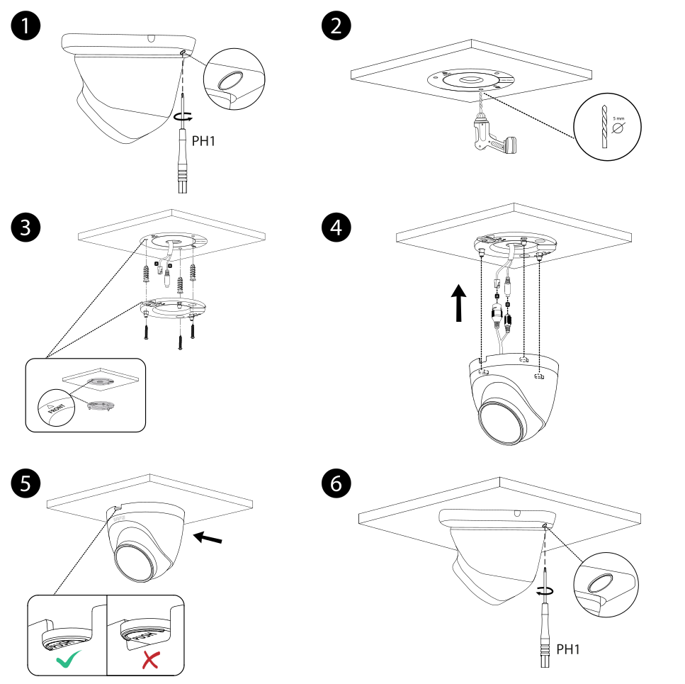
- Using a PH1 screwdriver, loosen the locking screw and remove the mounting plate from the camera.
- Place the drilling template on the mounting surface according to the marks FRONT a UP and drill 5 mm diameter holes. Also drill a hole for passing the cabling through.
- Insert wall plugs into the holes and screw on the mounting plate.
- Pass the cabling through the hole and connect the power and network connectors.
- Fit the camera onto the mounting plate.
- Set the viewing direction and tighten the locking screw with the PH1 screwdriver.
Cabling through the side outlet
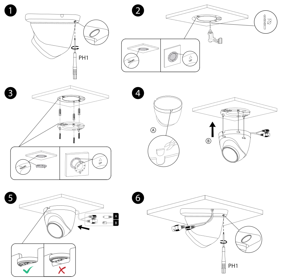
The procedure is the same as for installation with cabling through the mounting surface, except that the side cable outlet is broken out in the camera housing and the cable is routed along the surface of the mounting surface.
Waterproofing the connectors
Adjusting the viewing direction
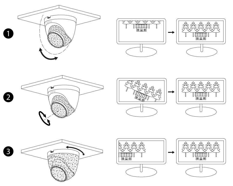
Tilt and rotate the camera body in the mounting plate so that the image covers the monitored area. The image can also be rotated in software – normal (0°), corridor mode (90° / 270°) or mirrored (180°).
Mounting methods
Functionality test
After installation, verify that the camera works correctly:
- Image – in the web interface, check the live image of both channels (visible and thermal) and adjust the viewing direction if necessary.
- Network – verify that the camera is available at the configured IP address and that it has appeared in the app.
- Temperature measurement – in the Event menu, check that temperature values are displayed in the defined zones.
- Alarm output – trigger a test event and verify that the connected device (siren, beacon) switches on.
- Intercom – verify two-way calling and voice message playback from the app.
Maintenance
- Keep the lenses clean – dust and dirt can be removed with an air blower, or gently wipe the lens with a soft cloth dampened with alcohol. Do not touch the sensor directly.
- Clean the camera body with a soft dry cloth; for stubborn stains, dampen it with a mild cleaning agent. Do not use volatile solvents (alcohol, benzene, thinner) or abrasive agents – they would damage the surface finish.
- Regularly check that the waterproof cable connections hold and that no water is leaking into them.
- Do not touch the heat dissipation part while the camera is in operation – there is a risk of burns.
- Do not disassemble the camera. When dismantling, follow the manual, otherwise there is a risk of water leakage or deterioration of image quality. Before fitting the cover, check that the sealing ring is flat and correctly seated in the groove.
- Update the firmware regularly and change the device password.
Technical specifications
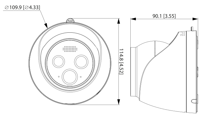
| Model designation | |
| SAFE 64220 | White version, EAN 0728204234891 |
| General properties | |
| Classification | Outdoor / indoor IP camera, turret type |
| Device type | Wired |
| Compatibility – apps | FireSAFE |
| Compatibility – Hubs | FireSAFE: 50HUB-WRF, 100HUB-WLRF |
| Temperature detection | Yes |
| Flame detection | Yes |
| Integrated microphone / speaker | Yes – built-in digital microphone / built-in speaker |
| Alarm signalling | Audible and visual (optional) |
| Privacy masking | Yes (4 areas) |
| Recording storage | NVR (HDD), FTP, NAS, SFTP |
| Interoperability | ONVIF, GB/T 28181, CGI |
| Browser support | IE 9 and later (Edge is not supported); Chrome 42 and earlier; Firefox 42 and earlier |
| Users / guests | Up to 10 connected simultaneously (available bandwidth 100 MB) |
| Security | Authorisation by username and password, MAC address binding, encrypted HTTPS protocol, IEEE 802.1x, network access control |
| Fault detection | Network disconnection; IP address conflict |
| Thermal chip | |
| Thermal sensor | Uncooled VOx (vanadium oxide) detector with high sensitivity |
| Effective resolution | 120 (H) × 90 (V) px |
| Pixel pitch | 17 µm |
| Spectral range | 8–14 µm |
| Sensor sensitivity (NETD) | < 60 mK (@f/1.0, 300 K) |
| Focal length / aperture | 1.2 mm / F1.1 |
| Field of view | H: 90°, V: 67,5° |
| Focus control | Fixed focus |
| Minimum focusing distance | 0,5 m |
| Temperature detection distance | 10 m (recommended) |
| Flame detection distance | 10 m, flame size 10 × 10 cm |
| Temperature detection range | −10 °C to +200 °C |
| Temperature detection accuracy | Max. ±5 °C or ±5 % |
| Temperature measurement unit | Adjustable (Celsius, Fahrenheit) |
| Temperature detection modes | Real-time spot temperature; three simultaneous rules (points, lines, polygons); temperature alarm; cold and hot spot alarm |
| Thermal noise reduction | 3D NR |
| Image flip | Normal; corridor mode (vertical); mirroring (horizontal) |
| Colour palette | 12 adjustable pseudo-colours |
| Optical chip | |
| Image sensor | 1/2.7" CMOS, 4 Mpx |
| Resolution | Up to 2688 × 1520 px @ 25 fps |
| Focal length / aperture | 4 mm / F1.6 |
| Lens type | Fixed, fixed focus |
| Field of view | H: 85°, V: 44°, D: 99° |
| Minimum focusing distance | 1 m |
| Scanning system | Progressive |
| Minimum illumination | Colour 0.0052 lx; black and white 0.0028 lx; 0 lx (active IR) |
| Electronic shutter | 1/3 s to 1/100,000 s (manual / automatic) |
| White balance | Automatic, outdoor, indoor, tracking, manual, natural, street lighting |
| AGC / noise reduction | Automatic or manual / 2D NR, 3D NR |
| S/N ratio | ≥55 dB |
| BLC / HLC / WDR | Yes / Yes / Yes (DWDR) |
| Exposure compensation | Yes |
| Day / night modes | Automatic (ICR); colour; black and white |
| Illuminator type and control | Adaptive infrared illuminator (1 IR LED); automatic or manual |
| Illuminator range | Do 15 m |
| Image flip | Normal (0°); corridor mode (90° / 270°); mirroring (180°) |
| Audio and video | |
| Video compression | H.265; H.264; H.264H; H.264B; MJPEG |
| Resolution – main stream | 4M (2688 × 1520); 1080p (1920 × 1080); 1.3M (1280 × 960); 720p (1280 × 720) — default 1920 × 1080 |
| Resolution – sub stream | D1 (704 × 576); VGA (640 × 480); CIF (352 × 288) — default 704 × 576 |
| Frame rate | Main and sub stream: 1–25 fps adjustable, default 25 fps |
| Audio compression | MPEG2-Layer2; G.711a; G.711mu; AAC; PCM; G.722.1; G.726 |
| Audio sampling | 8 kHz; 16 kHz |
| Video encoding format | JPEG |
| Ports and network | |
| Network port | 1× RJ-45, 10/100 Mb/s, with PoE support |
| Connection | Ethernet, 100 Mb/s |
| Alarm input | 1× channel: 5 mA, 3–5 V DC |
| Alarm output | 1× channel: 300 mA, 12 V DC |
| Alarm linkage | Switch activation – output / email / snapshots |
| General | |
| Power supply | 12 V DC (±30 %) or PoE |
| Power consumption | Basic 1.8 W; maximum 3 W |
| Power adapter | Optional accessories |
| Operating temperature | −10 °C to +55 °C |
| Operating humidity | Up to 95 % RH non-condensing |
| Storage conditions | −20 °C to +70 °C; 5–95 % RH non-condensing |
| Degree of protection | IP66 |
| Product dimensions | Ø 109.9 × 90.1 mm (overall height 114.8 mm) |
| Weight | 350 g |
| Colour | White |
| Certification | CE; FCC |
| Warranty | 36 months |
Package contents
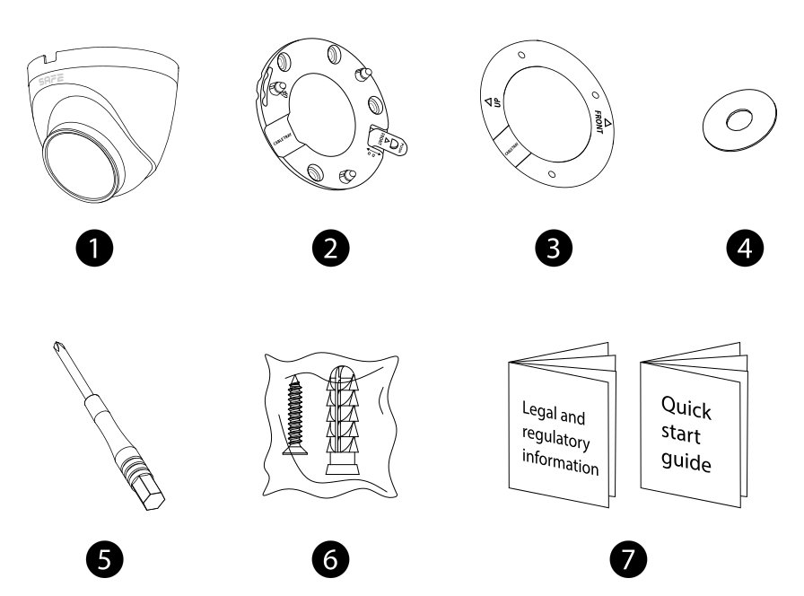
- Turret Cam AI camera – 1 pc
- Mounting plate – 1 pc
- Drilling template – 1 pc
- Sealing ring – 1 pc
- Screwdriver – 1 pc
- Bag of screws and wall plugs – 1 pc
- Documentation (quick user guide, legal and regulatory information) – 2 pcs
Safety notices
- Entrust installation and wiring to a qualified technician in accordance with local electrical safety regulations.
- Do not connect the camera to PoE and an external 12 V DC power supply at the same time.
- Operate and store the device only within the permitted temperature and humidity range (−10 °C to +55 °C, up to 95 % RH non-condensing).
- For outdoor installation, make all cable connections watertight.
- It is recommended to use the device together with lightning protection and to earth it.
- Keep the device password safe and do not disclose it to unauthorised persons – it gives access to the camera image and its settings.
- The camera is not a substitute for a certified electrical fire alarm system.
- Do not dispose of the product with ordinary municipal waste – hand it in for recycling in the electrical equipment take-back system.
Warranty
A warranty is provided on the SAFE Turret Cam AI device 36 months from the date of sale. The warranty does not cover defects caused by failure to follow the instructions in this manual, damage after purchase, unprofessional modification, incorrect use, poor maintenance or incorrect placement.
In case of problems with the device, first contact technical support – most situations can be resolved remotely.
Gallery
Need help?
SAFE HOME europe technical support:
E-mail: info@safe-home.eu · Telephone: (+420) 581 222 262
Web: www.smart-safe.eu