
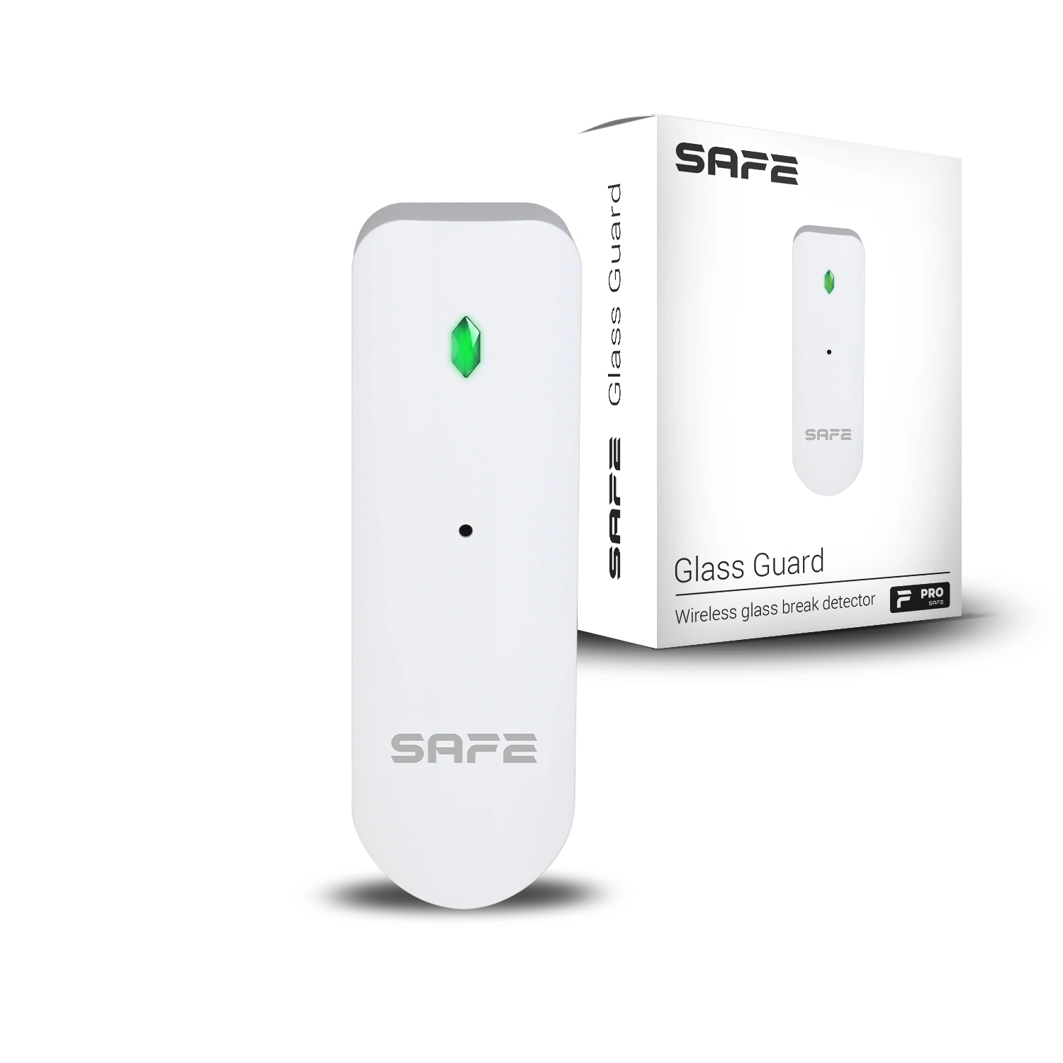
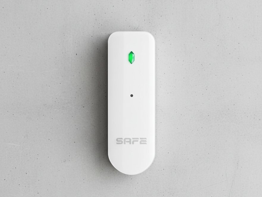
Glass Guard is a very small wireless glass break detector designed to protect glazed surfaces, equipped with two inputs for connecting wired detectors. Multi-factor glass break detection with remotely configurable sensitivity significantly reduces false alarms.
Foreword
General
This user manual describes the installation, functions and operation of the wireless glass break detector (hereinafter the “detector”). Read the manual carefully before using the device and keep it for future reference.
Safety instructions
The following signal words may appear in the user manual:
| Signal word | Meaning |
|---|---|
| NEBEZPEČÍ | Indicates a high potential hazard which, if not avoided, may result in death or serious injury. |
| VAROVÁNÍ | Indicates a medium or low potential hazard which, if not avoided, could result in minor or moderate injury. |
| UPOZORNĚNÍ | Indicates a potential risk which could lead to property damage, data loss, reduced performance or an unpredictable result. |
| TIP | Provides methods to help you solve a problem or save time. |
| POZNÁMKA | Provides additional information, such as emphasis or a supplement to the text. |
Revision history
| Version | Revision content | Release date |
|---|---|---|
| V1.0.0 | First release. | September 2026 |
| V1.0.1 | Text changes: Adding to the system, Installing the detector, Battery replacement, Package contents. | October 2026 |
| V1.0.2 | Names and order of items in Status and Settings aligned with the ProSAFE app (Weblate translations). | October 2026 |
| V1.0.3 | Photo gallery added. | October 2026 |
Privacy notice
As a user of the device or a data controller, you may collect the personal data of others, such as their face, fingerprints and licence plate number. You must comply with local privacy protection laws and regulations in order to protect the legitimate rights and interests of other people by taking measures which include, but are not limited to: providing clear and visible identification to inform people of the existence of the monitored area and providing the required contact information.
About the manual
- The user manual serves as a reference only. Minor differences may occur between the information provided and the product.
- We are not liable for damage resulting from use of the product in a manner that is not in accordance with the instructions in the user manual.
- The manual will be updated in line with the current laws and regulations of the relevant countries. For detailed information, see the printed user manual, scan the QR code or visit our website. The manual is for information purposes only. The electronic and printed versions may differ in minor details.
- All designs and software may be changed without prior written notice. As a result of product updates, certain differences may appear between the product and the information in the manual. The latest version of the software and supplementary documentation is available from customer service.
- Printing errors or deviations may occur in the description of functions, operations and technical data. In case of doubt or dispute, we reserve the right of final interpretation. If the manual (in PDF format) cannot be opened, update your reader software or try another common reader.
- All trademarks, registered trademarks and company names in the manual are the property of their respective owners.
- If any problems occur while using the device, visit our website, or contact your supplier or customer service.
- In case of ambiguity or dispute, we reserve the right of final interpretation.
Important precautions and warnings
This section contains information on the correct handling of the product, risk prevention and prevention of property damage. Read it carefully before using the device and follow the instructions provided while using it.
Operating requirements
- Before use, make sure the device's power supply is working properly.
- Do not unplug the device's power cable while it is switched on.
- Use the device only within its rated power range.
- Transport, use and store the device under the permitted humidity and temperature conditions.
- Prevent liquids from splashing or dripping onto the device. Make sure there are no objects filled with liquid on the device, to prevent liquids from entering it.
- Do not disassemble the device.
Installation requirements
- Connect the device to the power adapter before switching it on.
- Strictly comply with local electrical safety standards and make sure the voltage in the area is stable and matches the device's power requirements.
- Do not connect the device to more than one power source. Otherwise, the device could be damaged.
- When working at height, follow all safety procedures and use the required protective equipment.
- Do not expose the device to direct sunlight or sources of heat.
- Do not install the device in damp, dusty or smoky locations.
- Install the device in a well-ventilated location and do not block its ventilation.
- Use the power adapter or power supply provided by the device manufacturer.
- The power supply must meet the ES1 requirements of IEC 62368-1 and must not exceed PS2. The power supply requirements are governed by the device's rating label.
- Connect Class I electrical appliances to a socket with protective earthing.
Functional elements
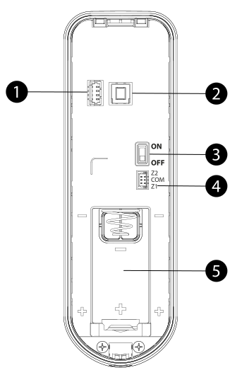
- Serial port – service interface for diagnostics; not used in normal operation.
- Tamper contact – raises an alarm when the detector is removed from the mounting panel.
- Power switch – switches the device on and off (ON / OFF position).
- External inputs connector – terminals Z1, COM and Z2 for connecting two wired detectors (see External wired inputs).
- Battery compartment – CR123A lithium battery.
Principle of operation
Glass Guard continuously monitors ambient sounds with a highly sensitive omnidirectional microphone and recognises the acoustic signature of breaking glass. As soon as the detector picks up both components of this sound, it sends an alarm event to the Hub and the user immediately receives a notification in the app ProSAFE.
Two-stage glass break detection
The detector evaluates the sound in two steps. First it picks up the characteristic low-frequency sound of an impact on a glass pane, and then the high-frequency sound of the glass breaking and shards shattering. The alarm is triggered only if both components are picked up in quick succession.
This makes the detector resistant to false alarms – for example, simply tapping on the glass panel of a door, a slammed door or street noise will not trigger an alarm.
Supported glass types
The detector reliably recognises the breaking of ordinary float glass as well as its toughened, tempered, wired, laminated and double-glazed versions.
| Glass parameter | Range |
|---|---|
| Glass type | Toughened, double-glazed, laminated, wired, plate and float |
| Glass thickness | 2.4–6.4 mm |
| Pane size | 0.3 × 0.3 m to 3 × 3 m |
| Detection range | Max. 9 m |
Adjustable sensitivity
Detection sensitivity is set remotely in the ProSAFE app at three levels – low, medium a high. The higher the value, the more easily the detector raises an alarm. Verify the setting using test mode directly at the installation site.
Abnormal temperature alarm
The integrated temperature sensor measures the ambient temperature at the installation site in the range −15 °C to +65 °C with an accuracy of ±1 °C. A minimum and maximum temperature limit can be defined in the settings – if either is exceeded, the detector raises an alarm, and when the temperature returns to the set range it sends information that normal conditions have been restored.
SAFE Keeper protocol
Communication with the Hub is provided by an encrypted two-way radio protocol SAFE Keeper in the 868 MHz band:
- AES128 data encryption with a rolling code,
- frequency hopping as protection against jamming,
- range of up to 1,600 m in open space,
- two-way communication between the detector and the Hub.
External wired inputs
The detector has two potential-free inputs, which can be used to connect wired detectors to the SAFE wireless system – including those from other manufacturers. These are typically flammable gas detectors, armoured garage door contacts, flood detectors or PIR motion sensors.
The wires of the supplied connecting cable correspond to the terminals as follows:
| Terminal | Cable wire | Meaning |
|---|---|---|
| Z1 | red | External input 1 |
| COM | black | Common wire for both inputs |
| Z2 | white | External input 2 |
Each input is configured separately in the ProSAFE app – as NO (normally open), NC (normally closed) or Pulse. An input can be set as a standard sensor or as a tamper contact, assigned to a 24-hour zone and linked to a siren.
Adding to the system
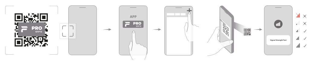
Before adding the device
- Install the ProSAFE app and log in to your account.
- Make sure you have a compatible Hub added in the app (Hub 2 Plus LTE, SAFE 38300) with a stable internet connection.
- The Hub must be in the Disarmed.
How to add Glass Guard
- In the ProSAFE app, open your Hub and tap Device.
- Tap + Add device.
- Scan the QR code with the serial number on the underside of the detector and tap Next.
- Once the detector has been found, tap Next.
- Following the on-screen instructions, switch the detector on by moving the power switch to the ON position and tap Next.
- Wait for the pairing to complete.
- Enter a name for the detector, select an area (zone) and tap Done.
Statuses
To view the current status of the detector, select it in the device list in the ProSAFE app.
| Parameter | Meaning |
|---|---|
| Temperature | Current ambient temperature at the installation site |
| Signal strength | Radio signal level: none / low / weak / good / excellent |
| Connection status | Connection between the detector and the Hub
|
| Battery Level | Fully charged / sufficient / medium / insufficient / low |
| Bypass | Enable / Disable tamper alarm only / Disable |
| Tamper | Status of the detector's tamper contact |
| Sensitivity | Set sensitivity level for glass break detection |
| Exit / entry delay | Set delay time for leaving and entering the area |
| 24-hour zone status | Whether continuous protection is enabled regardless of system arming |
| Repeater | Whether the detector communicates with the Hub via a signal repeater |
| External input | Status of external input channels 1 and 2 (displayed once external detector configuration is enabled) |
| Firmware version | Current firmware version of the detector |
Settings
To change the settings in the ProSAFE app, select the detector in the device list and tap the edit icon.
| Settings | Value |
|---|---|
| Device | Custom name of the detector; shown in the device list and in notifications |
| Area | Assignment of the detector to an area of the system |
| Bypass | Enable (default) / Disable tamper alarm only / Disable |
| LED indicator | On (default) / off – when switched off, the LED does not light regardless of the device status |
| Temperature limit alarm | Alarm when the set temperature range (min/max) at the installation site is exceeded |
| Home Armed mode | Enabling Home Armed mode – selected devices under the Hub remain armed |
| Siren linkage | The siren sounds when this detector raises an alarm |
| Alarm and video linkage | When an alarm is raised, the selected video channel is linked and the alarm video is saved |
| Video channel | Selection of the video channel to be linked with the alarm |
| Sensitivity | Low / medium / high – the higher the value, the more easily an alarm is raised |
| Signal strength test | Verifying the quality of the radio connection at the installation site |
| Detector test | Starting the glass break detection test mode |
| Zone number | Zone number assigned to the detector's alarm; cannot be changed |
| 24-hour zone | On – the detector keeps watch even when the system is disarmed / off – it keeps watch only when the system is armed |
| Delay in Home Armed mode | The alarm is raised only after the set delay has elapsed; requires Home Armed mode to be enabled |
| Delay time | Delay for entering and leaving the area, 0–120 s
|
| External detector configuration | Enabling and configuring external inputs 1 and 2 – sensor type (sensor / tamper), input type (NO / NC / Pulse), 24-hour zone and siren linkage |
| Transmission power | High / low / automatic – higher power extends the range but increases consumption
|
| Firmware update | Remote firmware update |
| Remove | Deleting the detector from the system (swipe left in the device list) |
Signalling
| LED indication | Event |
|---|---|
| Flashes green briefly 3× (lit for 0.25 s, off for 0.25 s) | The detector has entered test mode |
| Lit green for 0.5 s | In test mode, a low-frequency signal (impact on the glass) was picked up |
| Lit green for 3 s | In test mode, a high-frequency signal (shattering glass) was picked up |
| Flashes when transmission power is set to Low | The device is operating in reduced sensitivity mode |
| Off | The LED indicator is switched off in the settings, or the device is switched off |
Choosing the installation location
Place the detector in a room with glazed surfaces so that it has a clear line of sight to the protected glass and nothing is obstructing the view between it and the glass – not even partially.
Recommended location

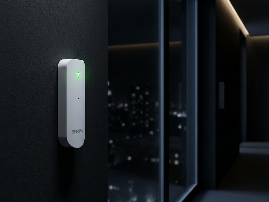
- Adjacent wall – recommended location; the detector has a side view of the glass surface.
- Opposite wall – suitable if nothing stands between the detector and the glass.
Installation distance
The maximum detection range is 9 m. For ordinary and plate glass measuring 3 × 3 m, we recommend a distance between the detector and the protected glass of up to 6 m.
Where not to install the detector
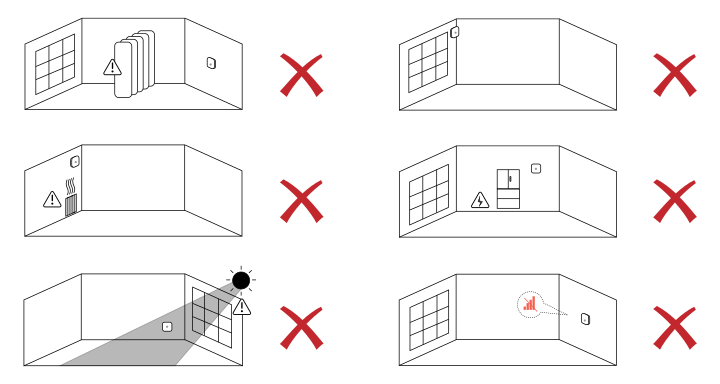
- Where furniture, a curtain, a blind or another obstruction blocks the view of the protected glass.
- On the same wall as the protected glass surface.
- Near ventilation, air conditioning and other sources of constant noise.
- Near high-current equipment and distribution boards.
- In places exposed to direct sunlight or near heat sources.
- In damp, dusty or smoky areas.
- In places with a weak radio signal from the Hub.
Signal strength
Before final installation, test the signal strength in the app (Signal strength test). If the signal is weak, move the detector or use a signal repeater.
Installing the detector
The detector is surface-mounted on the wall using the supplied mounting panel. Before drilling, we recommend placing the device temporarily and checking the signal strength and the detector's response at the installation site.
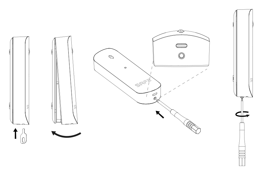
- Using the supplied cover opening tool remove the detector from the mounting panel.
- Remove the protective film from the battery compartment and switch on the detector using the power switch.
- Add the detector to the system (see Adding to the system) and verify the signal strength and the detection test at the planned location.
- If required, connect the supplied connecting cable of wired detectors to terminals Z1, COM and Z2 (see External wired inputs).
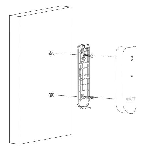
- Fix the mounting plate to the wall – either with the supplied double-sided adhesive tape, or with the screws and wall plugs from the mounting kit.
- Place the detector on the mounting plate and secure it with the supplied screw. Use a screwdriver to tighten it.
Functionality test
After installation, verify that the detector works correctly at the place of installation:
- Signal strength test – in the app, run a test and check the quality of the radio connection with the Hub.
- Detector test – in the app, tap Start detection. The detector confirms entry into test mode with three short LED flashes.
- In test mode strike the glass with your fist or a rubber ball (do not break the glass). The LED lights up for 0.5 s – a low-frequency signal has been detected.
- Within 10 seconds then strike the glass with a metal object (do not break the glass), or use a glass-break sound simulator. The LED lights up for 3 s – a high-frequency signal has been detected.
Battery replacement
The detector is powered by 1× CR123A lithium battery (3 V). Battery life is up to 3 years with an external NO-type input, or approximately 1 year with both inputs enabled as NC type. The ProSAFE app warns you of a low battery.
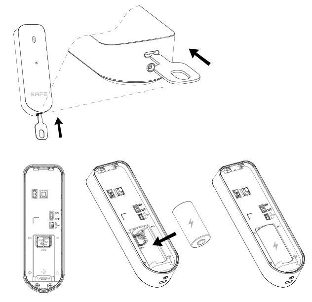
- Loosen the locking screw.
- Use the supplied tool to remove the detector from the mounting plate and switch it off with the power switch.
- Remove the depleted battery.
- Insert a new CR123A battery. Observe the correct polarity.
- Switch the device on with the power switch and place the detector back on the mounting plate.
Maintenance
- Keep the microphone grille clean – dust and dirt reduce the sensitivity of acoustic detection. Wipe it with a dry, soft cloth and do not use aggressive cleaning agents.
- Make sure that nothing blocks the detector's view of the protected glass – check its position after rearranging furniture, hanging a curtain or installing a roller blind.
- Regularly check the battery status and signal strength in the ProSAFE app.
- Carry out a detection test after every handling of the detector.
- Do not disassemble the detector.
Technical specifications
| Model designation | |
| SAFE 38120 | White version, EAN 0728204234754 |
| Detection parameters | |
| Detection type | Acoustic, two-stage (low-frequency and high-frequency signal) |
| Sensor | Highly sensitive omnidirectional microphone |
| Detection range | Max. 9 m |
| Glass type | Toughened, double-glazed, laminated, wired, sheet, float |
| Glass thickness | 2.4–6.4 mm |
| Pane size | 0.3 × 0.3 m to 3 × 3 m |
| Sensitivity | Adjustable in 3 levels (low / medium / high) |
| Temperature sensor | |
| Measuring range | −15 °C to +65 °C (indoor) |
| Accuracy / resolution | ±1 °C / 1 °C |
| Inputs and outputs | |
| Alarm input | 2× NC / NO potential-free (adjustable, also supports Pulse mode) |
| Wireless transmission – SAFE Keeper | |
| Carrier frequency | 868.0–868.6 MHz |
| Transmitter power (EIRP) | limit 25 mW |
| Communication range | Up to 1,600 m in open space |
| Communication type | Two-way |
| Encryption | AES128 |
| Frequency hopping | Yes (automatic) |
| Interfaces and functions | |
| Indication | 1× green LED |
| Controls | 1× power button (switch) |
| Tamper contact | Yes (tamper) |
| Remote update | Yes (cloud) |
| Low battery warning | Yes |
| Search | Signal strength detection |
| Test Mode | Yes – signal strength test and detection test |
| General | |
| Power supply | 1× CR123A battery, 3 V (included in the package) |
| Power consumption | Max. 150 mW |
| Current consumption | ≤45 µA (operation), ≤50 mA (alarm) |
| Battery life | 3 years (external input NO); 1 year (both external inputs enabled, type NC) |
| Operating temperature | −10 °C to +55 °C (indoor) |
| Operating humidity | 10–90 % RH |
| Housing material | PC + ABS, white |
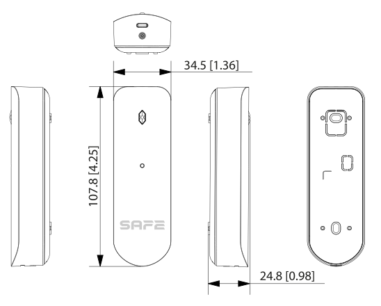
| Product dimensions | 107.8 × 34.5 × 24.8 mm (L × W × H) |
| Package dimensions | 95 × 43 × 139 mm (L × W × H) |
| Weight | Net 45 g / gross 130 g |
| Installation | On mounting plate (adhesive tape or screws) |
| Compatibility | Hub 2 Plus LTE (SAFE 38300) |
| Certification | CE |
| Security grade / environmental class | Grade 2 / class II |
| Warranty | 36 months |
Package contents
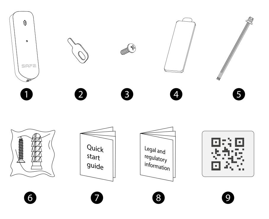
- Glass Guard detector – 1 pc
- Cover opening tool – 1 pc
- Locking screw – 1 pc
- Double-sided adhesive tape – 1 pc
- External input connecting cable – 1 pc
- Mounting kit (screws, wall plugs) – 1 set
- Quick user guide – 1 pc
- Legal and regulatory information – 1 pc
- QR code with user manual – 1 pc
Safety notices
- Operate and store the device only within the permitted temperature and humidity range (−10 °C to +55 °C, 10–90 % RH).
- The detector is intended for indoor use only.
- Do not install the detector in places exposed to direct sunlight or near heat sources.
- Prevent liquids from splashing or dripping onto the device.
- Keep batteries out of the reach of children. Do not throw batteries into a fire, crush them or cut them open – there is a risk of explosion. If you suspect that a battery has been swallowed, seek medical help immediately.
- Replace a depleted battery only with a battery of the same type (CR123A).
- Do not dispose of the product with ordinary municipal waste – hand it in for recycling in the electrical equipment take-back system.
Warranty
The SAFE Glass Guard device is covered by a warranty of 36 months from the date of sale. The warranty does not cover the battery or defects caused by failure to follow the instructions in this manual.
In case of problems with the device, first contact technical support – most situations can be resolved remotely.
Gallery
Need help?
SAFE HOME europe technical support:
E-mail: info@safe-home.eu · Telephone: (+420) 581 222 262
Web: www.smart-safe.eu