
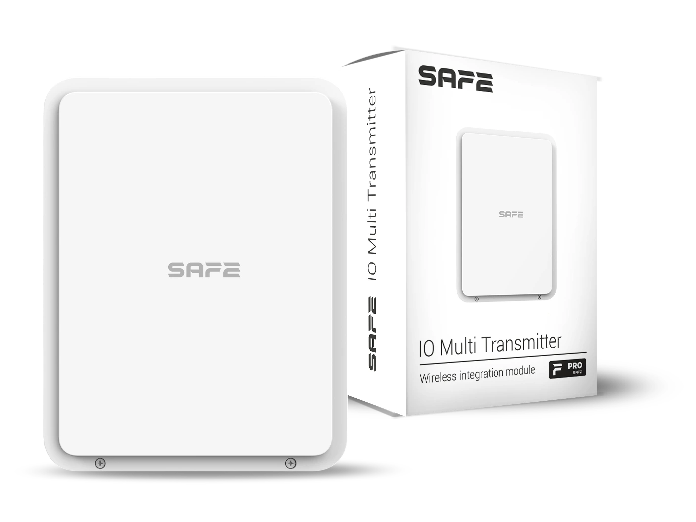
IO Multi Transmitter is an integration module with 20 wired zones, which makes it possible to modernise existing installations of alarm security systems from other manufacturers without having to replace functional equipment. At the same time, it opens up the possibility of extending the SAFE system with almost any wired security device. Connected devices gain management through the ProSAFE app, automation scenes and detailed notifications to the phone.
Foreword
General
This user manual describes the installation, functions and operation of the wired device integration module (hereinafter the “module”). Read the manual carefully before using the device and keep it for future reference.
Safety instructions
The following signal words may appear in the user manual:
| Signal word | Meaning |
|---|---|
| NEBEZPEČÍ | Indicates a high potential hazard which, if not avoided, may result in death or serious injury. |
| VAROVÁNÍ | Indicates a medium or low potential hazard which, if not avoided, could result in minor or moderate injury. |
| UPOZORNĚNÍ | Indicates a potential risk which could lead to property damage, data loss, reduced performance or an unpredictable result. |
| TIP | Provides methods to help you solve a problem or save time. |
| POZNÁMKA | Provides additional information, such as emphasis or a supplement to the text. |
Revision history
| Version | Revision content | Release date |
|---|---|---|
| V1.0.0 | First release. | September 2026 |
| V1.0.1 | Names and order of items in Status and Settings aligned with the ProSAFE app (Weblate translations). | October 2026 |
| V1.0.2 | Technical specifications corrected according to the manufacturer's documents. | October 2026 |
| V1.0.3 | Photo gallery added. | October 2026 |
| V1.0.4 | Text changes: Module installation, Adding to the system, Package contents. | October 2026 |
Privacy notice
As a user of the device or a data controller, you may collect the personal data of others, such as their face, fingerprints and licence plate number. You must comply with local privacy protection laws and regulations in order to protect the legitimate rights and interests of other people by taking measures which include, but are not limited to: providing clear and visible identification to inform people of the existence of the monitored area and providing the required contact information.
About the manual
- The user manual serves as a reference only. Minor differences may occur between the information provided and the product.
- We are not liable for damage resulting from use of the product in a manner that is not in accordance with the instructions in the user manual.
- The manual will be updated in line with the current laws and regulations of the relevant countries. For detailed information, see the printed user manual, scan the QR code or visit our website. The manual is for information purposes only. The electronic and printed versions may differ in minor details.
- All designs and software may be changed without prior written notice. As a result of product updates, certain differences may appear between the product and the information in the manual. The latest version of the software and supplementary documentation is available from customer service.
- Printing errors or deviations may occur in the description of functions, operations and technical data. In case of doubt or dispute, we reserve the right of final interpretation. If the manual (in PDF format) cannot be opened, update your reader software or try another common reader.
- All trademarks, registered trademarks and company names in the manual are the property of their respective owners.
- If any problems occur while using the device, visit our website, or contact your supplier or customer service.
- In case of ambiguity or dispute, we reserve the right of final interpretation.
Important precautions and warnings
This section contains information on the correct handling of the product, risk prevention and prevention of property damage. Read it carefully before using the device and follow the instructions provided while using it.
Operating requirements
- Before use, make sure the device's power supply is working properly.
- Do not unplug the device's power cable while it is switched on.
- Use the device only within its rated power range.
- Transport, use and store the device under the permitted humidity and temperature conditions.
- Prevent liquids from splashing or dripping onto the device. Make sure there are no objects filled with liquid on the device, to prevent liquids from entering it.
- Do not disassemble the device.
Installation requirements
- Connect the device to the power adapter before switching it on.
- Strictly comply with local electrical safety standards and make sure the voltage in the area is stable and matches the device's power requirements.
- Do not connect the device to more than one power source. Otherwise, the device could be damaged.
- When working at height, follow all safety procedures and use the required protective equipment.
- Do not expose the device to direct sunlight or sources of heat.
- Do not install the device in damp, dusty or smoky locations.
- Install the device in a well-ventilated location and do not block its ventilation.
- Use the power adapter or power supply provided by the device manufacturer.
- The power supply must meet the ES1 requirements of IEC 62368-1 and must not exceed PS2. The power supply requirements are governed by the device's rating label.
- Connect Class I electrical appliances to a socket with protective earthing.
Functional elements
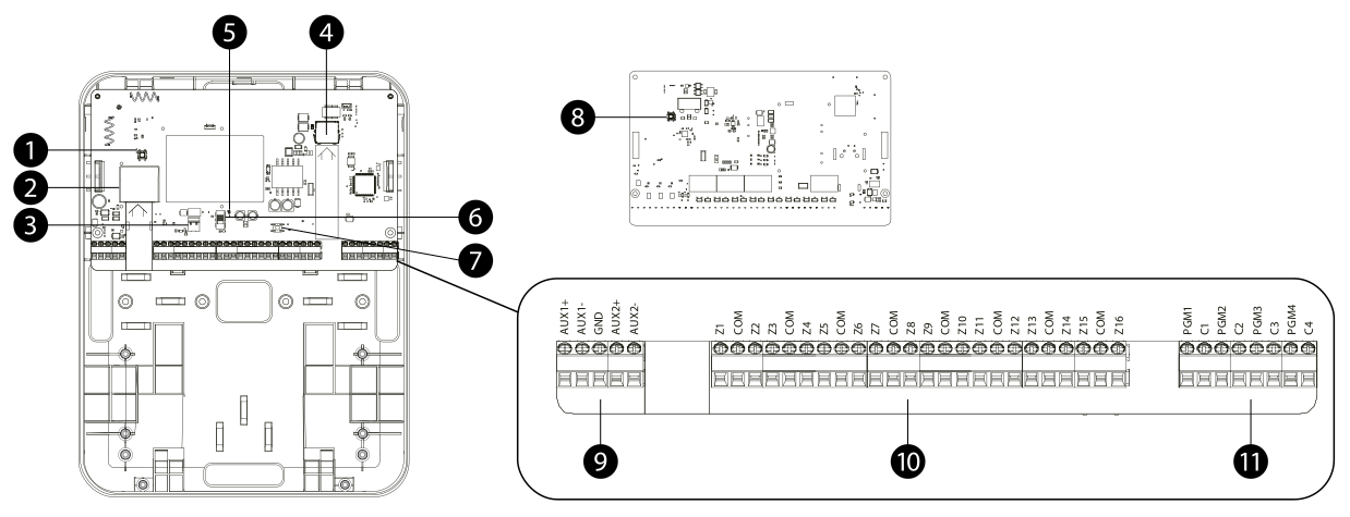
- Enclosure tamper contact – responds to the box being opened.
- Mains power terminal block – 100–240 V AC supply.
- Backup battery terminals – connection of a 12 V battery.
- RJ-45 network port – connection to the Ethernet network and, at the same time, PoE power supply.
- LED indicator – shows the status, pairing and communication.
- Operating mode button – switches the module's power on and off.
- Reset button – restores the module's factory settings.
- Wall tamper contact – responds to the module being torn off the mounting surface.
- Auxiliary power output terminals – AUX1+, AUX1−, GND, AUX2+, AUX2− for powering the connected detectors.
- Input terminal block – Z1 to Z16 for connecting wired detectors.
- Output terminal block – C1 to C4 and PGM1 to PGM4 for relay outputs.

Principle of operation
The module converts signals from wired detectors and control elements into SAFE system events and vice versa – it switches external devices using relay outputs. It reports to the system as a single device, but each input and output is individually addressable: it has its own name, area and alarm type.
Two communication channels
The module communicates with the Hub either wirelessly using the SAFE Keeper protocol in the 868 MHz band, or over Ethernet via the RJ-45 port (10/100 Mb/s). The wired connection ensures instant data transmission and is suitable where it is not possible to rely on radio signal propagation alone.
Alarm inputs
Sixteen fully programmable inputs make it possible to connect any wired security and automation devices – PIR motion detectors, magnetic contacts, detectors and sensors, thermostats and more. In addition, channels 1 to 6 can handle pulse detection.
Each input can be set as a sensor, tamper contact or key switch and assigned an alarm type: intrusion, fire, medical assistance, panic button, gas leak or water leak. As a result, both the notification and the message to the DPPC describe the location and type of incident precisely.
Compatibility with wired devices
The module supports wiring NO, NC, 1EOL, 2EOL i 3EOL. The end-of-line resistor is selected according to what the loop is to monitor:
| Wiring | What for |
|---|---|
| 0EOL (NO / NC) | Simple loop without line supervision |
| 1EOL | Line supervision without detector tamper alarm |
| 2EOL | Line supervision including tamper alarm |
| 3EOL | Line supervision including tamper alarm, masking alarm and fault |
With 1EOL wiring, the resistance value can be selected in the app 1.1 kΩ, 2.2 kΩ, 4.7 kΩ, 5.6 kΩ, 6.8 kΩ or 8.2 kΩ, or a custom value in the range 1–15 kΩ.
Alarm outputs and scenes
Four programmable relay outputs (NO/NC, max. 30 V DC / 3 A) are used to control external circuits – sirens, beacons, electric locks, roller shutters, ventilation or lighting. Each output works in bistable mode (holds its state until switched) or pulse mode (default pulse length 30 s, max. 600 s).
Outputs can be linked to scenes: arming or disarming of areas, a device alarm, or a time schedule.
Choosing the installation location
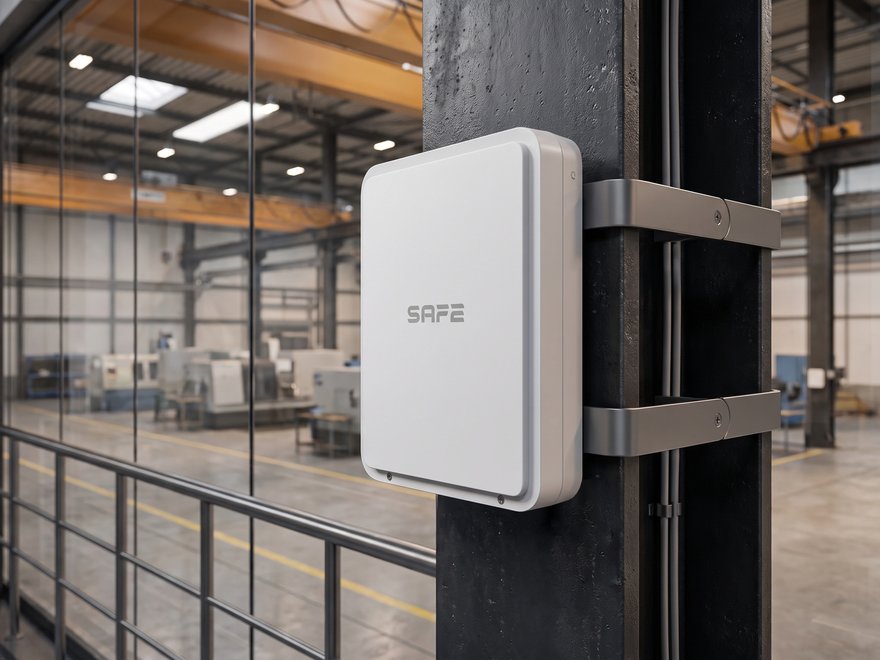
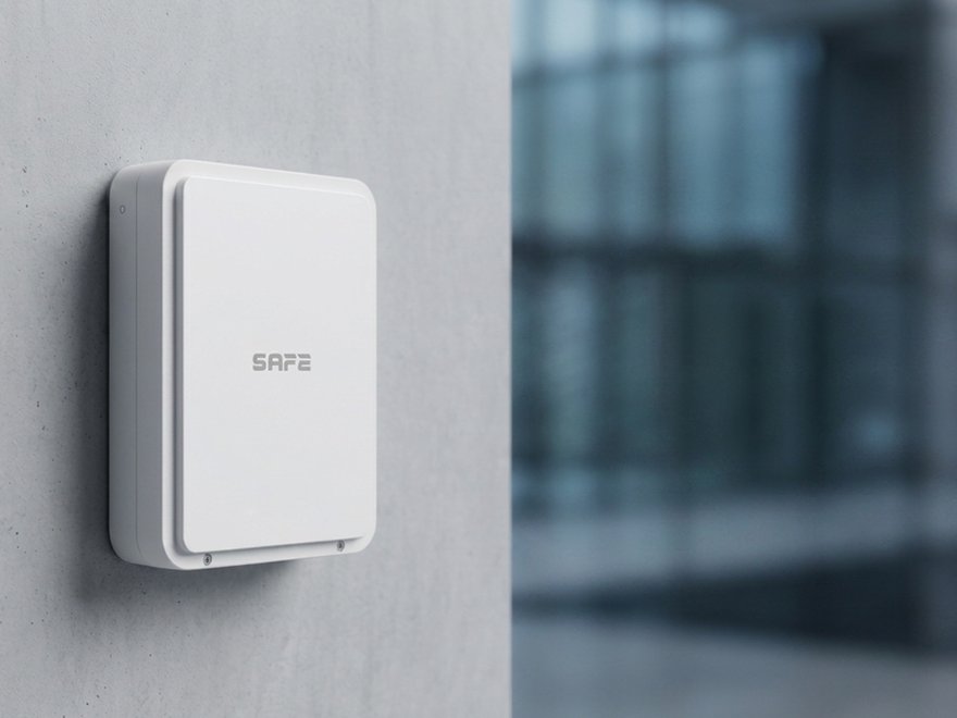
The module is intended for indoor use only (IP30 protection rating). It is mounted on a wall or in a switchboard.
- Choose a location within range of the Hub's radio signal, or where the network cable can reach.
- Allow space for a 12 V / 7 Ah backup battery inside the box.
- The cabling to the detectors may be up to 500 m long (cable type, for example, RVV2×2.8).
- Do not install the module in damp, dusty or smoky areas.
- Do not install it in places exposed to direct sunlight or near heat sources.
- Do not cover the ventilation openings of the box.
Module installation
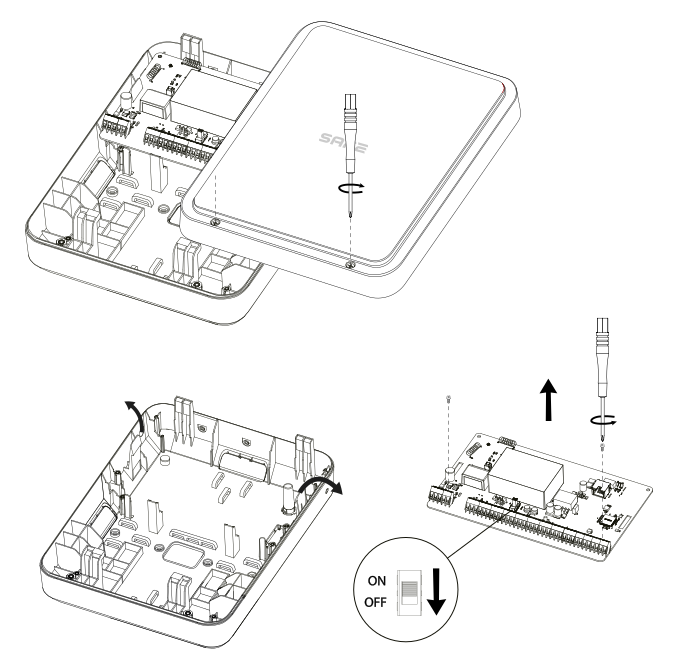
- Loosen the two screws on the front panel and open the panel.
- Release the catches, undo the two screws of the board and remove the board.
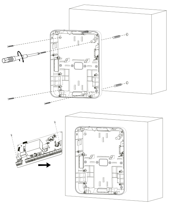
- Fix the rear panel to the wall using the screws supplied.
- Insert the board back into the rear panel.
- Carry out the wiring (see Wiring).
- Add the module to the system (see Adding to the system).
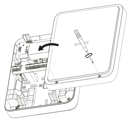
- Fit the front panel and tighten the screws.
Wiring
Alarm inputs
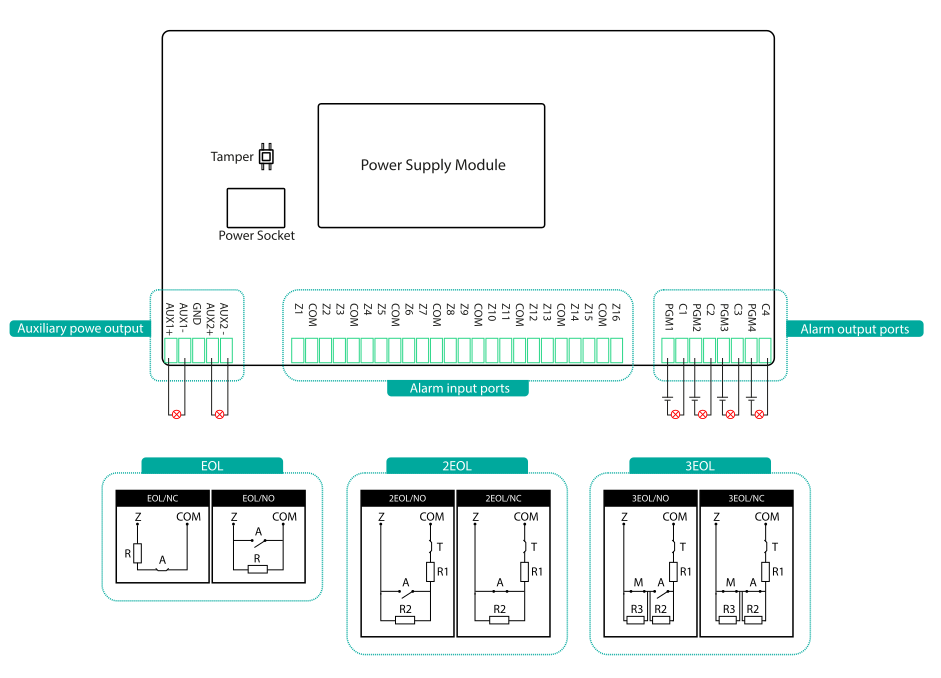
The sixteen inputs correspond to terminals Z1 to Z16. Choose the wiring according to what the loop is to monitor (see the table in the chapter Principle of operation).
Alarm outputs
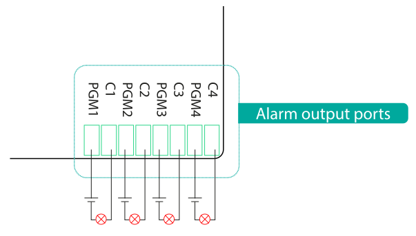
The four outputs correspond to the terminal pairs C1–C4 a PGM1–PGM4.
Auxiliary power outputs
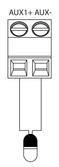
The two auxiliary outputs correspond to terminals AUX1+, AUX1−, GND, AUX2+ a AUX2− and are used to power connected detectors with a voltage of 14,5 V. The total current of both outputs depends on how the module is powered:
| Module power supply | Total current of both auxiliary outputs |
|---|---|
| 100–240 V AC or 12 V / 7 Ah battery | 14,5 V / 2 A |
| PoE | 14,5 V / 1 A |
Power supply and backup
The module can be powered in three ways:
- from the mains 100–240 V AC, 50/60 Hz,
- via PoE (802.3at),
- z an external battery 12 V.
In the event of a power failure, the connected battery keeps the system running – in static standby mode for up to 30 hours. The module itself detects a low battery level: the discharge threshold is 11.5 V, the recovery threshold 12 V.
Adding to the system
Before adding the device
- Install the ProSAFE app and log in to your account.
- Make sure you have a compatible Hub added in the app (Hub 2 Plus LTE, SAFE 38300) with a stable internet connection.
- The Hub must be in the Disarmed.


Adding by radio
- In the ProSAFE app, open your Hub and tap Device.
- Tap + Add device and scan QR code on the underside of the module. Tap Next.
- When the module is found, tap Next.
- Follow the on-screen instructions to switch the module on and tap Next.
- Wait for the pairing to complete.
- Enter the module name, select an area and tap Done.
Adding over the network
- In the app, open the Hub and tap Device.
- Tap +, select Add device and scan the QR code on the rear panel of the module. Tap Next.
- Enter the module name and area and tap Next.
- Tap … at the top right, select Add via network position and tap Next.
- When the module is found, enter and confirm the password and tap Next.
- Wait for pairing to complete and tap Done.
Wired devices
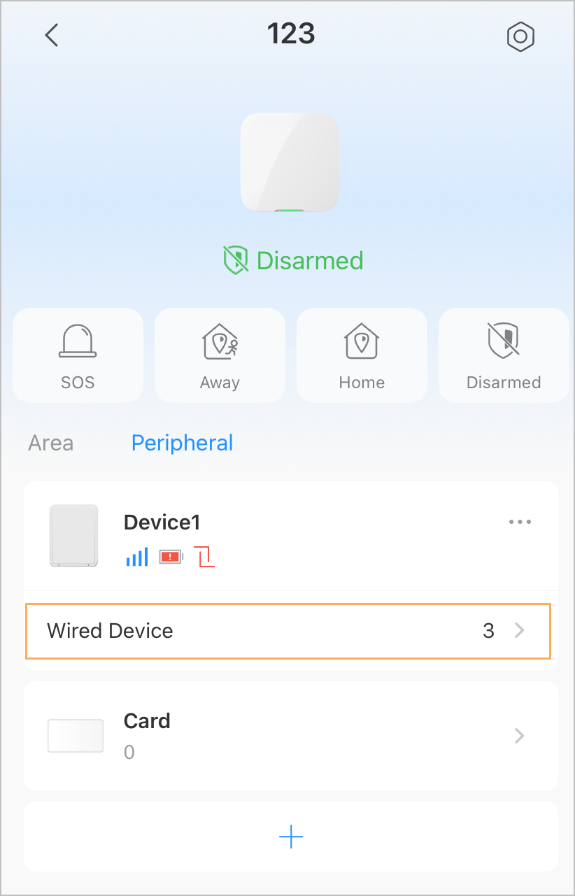
Adding a wired device
- Connect the detector or controlled element to the module as described in the chapter Wiring.
- In the app, open the Hub and select Device.
- Tap Wired devices and then tap + at the top right.
- Enter a name, select an area and the device type:
- Input – select a channel Input 1 up to Input 16, which correspond to terminals Z1 to Z16.
- Output – select a channel Output 1 up to Output 4, which correspond to terminals C1 to C4.
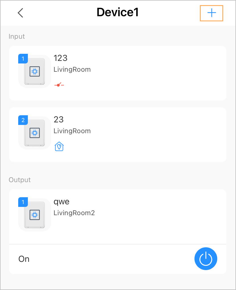
Input settings
| Settings | Value |
|---|---|
| Name / Area | Custom name of the input and its assignment to a system area |
| External detector type | Sensor / Tamper / Key switch |
| Contact type | Normally open / Normally closed / Pulse |
| EOLR | None / 1 / 2 / 3 |
| Resistance value | With EOLR = 1: 1.1 / 2.2 / 4.7 / 5.6 / 6.8 / 8.2 kΩ, or a custom value of 1–15 kΩ |
| Alarm type | Intrusion / Fire / Medical assistance / Panic button / Gas leak / Water leak (Sensor type) |
| Zone type | Instant / Delayed / 24-hour (Sensor type) |
| Home Armed mode | When the system is armed in Home Armed mode, the input is monitored only if this option is enabled |
| Chime | When the zone is disarmed, the siren sounds a chime when the input is triggered |
| Siren linkage | The siren sounds when this input raises an alarm |
| Video linkage / Video channel | When an alarm is raised, the selected video channel is linked and the alarm video is saved |
| Bypass | Yes / Cover only / No — the bypass is cancelled automatically once the system is disarmed |
| Permanent bypass | Yes / Cover only / No |
| Permission and control mode | Areas and control method (Key switch type): by the number of switchings, or by the state of the switch |
| Detection test | Verification of the signal of the connected input device |
Output settings
| Settings | Value |
|---|---|
| Name / Area | Custom name of the output and its assignment to a system area |
| Output type | Normally open / Normally closed |
| Output mode | Bistable / Pulse (default pulse length 30 s, max. 600 s) |
| Scenes | Linkage with arming and disarming of areas, with a device alarm, or with a time schedule |
| Bypass / Permanent bypass | Yes / Cover only / No |
Statuses
You can view the module's current status in the ProSAFE app by selecting the module in the device list.
| Parameter | Meaning |
|---|---|
| Device number | Serial number of the module in the system |
| Connection status | Online – the module is communicating / Offline – connection lost |
| Signal strength | Radio signal level: none / low / weak / good / excellent (only for modules added by radio) |
| Repeater | Whether the module communicates with the Hub via a signal repeater (only for modules added by radio) |
| External power status | Connected / Disconnected |
| Battery Level | Fully charged / sufficient / medium / insufficient / low / no battery |
| Tamper | Status of the enclosure and wall tamper contacts |
| Auxiliary power output | Normal / Overload (short circuit in the line or capacity exceeded) |
| Number of wired devices | Total number of configured wired channels |
| Bypass / Permanent bypass | Yes / Cover only / No |
| Input status | Normal / cover open / shorted loop / broken loop / masked |
| Output status | On / Off |
| 24-hour zone status | Whether 24-hour protection is enabled for the input |
Settings
To change the settings, in the ProSAFE app select the module in the device list and tap the edit icon.
| Settings | Value |
|---|---|
| Device | Custom name of the module; it is displayed in the device list and in notifications |
| Area | Assignment of the module to a system area |
| Bypass | Yes – information is not sent to the Hub / Cover only – everything except tamper alarms is sent / No (default). Once the system is disarmed, the bypass is cancelled automatically |
| Permanent bypass | Yes / Cover only / No |
| Signal strength test | Verifying the quality of the radio connection at the installation site |
| Transmission power | High / low / automatic – higher power extends the range but increases consumption. If Low is selected, the indicator flashes |
| Firmware update | Remote firmware update. For a module with Ethernet, we recommend updating over the network, or manually on the local network using the ConfigTool utility |
Functionality test
After installation, verify that the module works correctly:
- Signal strength test – for a module added by radio, run the test and verify the quality of the connection to the Hub.
- Detector test – for each configured input, run the test and verify that the connected device responds.
- Inputs – trigger an alarm on each connected detector in turn and check that an event with the correct name, area and alarm type appears in the app.
- Outputs – from the app, switch each output and verify that the connected device responds.
- Tamper – open the cover and verify that the module reports a tamper alarm.
- Backup – disconnect the mains power supply and verify that the module stays online and the Hub reports an external power failure.
Maintenance
- Regularly check the condition of the backup battery and, if necessary, replace it with one of the same type.
- Check that the terminals are tight and the cabling is in good condition – a loose connection will show up as a loop fault.
- Wipe the box with a dry, soft cloth. Do not use aggressive cleaning agents.
- Do not cover the ventilation openings of the box.
- After any handling of the module or cabling, carry out a functionality test.
Technical specifications
| Model designation | |
| SAFE 38190 | White version, EAN 0728204235546 |
| Classification | |
| Classification | Wired device integration module |
| Use | Indoor environment |
| Interface | |
| Optical indication | 1× built-in LED indicator |
| Inputs | 16 alarm input channels – programmable (channels 1–6 pulse detection) |
| Outputs | 4 alarm output channels (relay, max. 30 V DC / 3 A) |
| Communication line | Cabling up to a max. length of 500 m, cable type for example RVV2×2.8 |
| Buttons | 1× operating mode button, 1× Reset button |
| Network port | 1× RJ-45, 10/100 Mb/s Ethernet, with PoE support |
| Line configuration | NC, NO, 1EOL, 2EOL, 3EOL and pulse |
| EOLR support | with EOLR = 1: 1.1 kΩ, 2.2 kΩ, 4.7 kΩ, 5.6 kΩ, 6.8 kΩ, 8.2 kΩ, or a custom value of 1–15 kΩ |
| Operating mode | Pulse, bistable |
| Functions | |
| LED indicator | Status display, pairing, communication |
| Low battery capacity detection | Yes |
| Remote update | Yes (cloud) |
| Tamper contact | Yes (cover and wall tamper) |
| Wireless transmission – SAFE Keeper | |
| Carrier frequency | 868.0–868.6 MHz |
| Transmitter power (EIRP) | limit 25 mW |
| Communication range | Up to 1,600 m in open space |
| Communication type | Two-way |
| Encryption | AES128 |
| Frequency hopping | Yes (automatic) |
| Power supply | |
| Power supply | 100–240 V AC, 50/60 Hz; PoE (802.3at); 12 V DC backup battery |
| Backup battery | 12 V / 7 Ah – recommended, not included in the package |
| Standby time | Static standby mode up to 30 hours |
| Battery discharge / recovery threshold | 11,5 V / 12 V |
| Auxiliary outputs | 2 integrated 14.5 V outputs, 1 A in total (PoE) or 2 A (without PoE) |
| Power consumption with 220 V AC supply | Quiescent current 40 mA (Irms); max. 315 mA (Irms) at a 2 A load and while charging |
| Power consumption with PoE supply | Quiescent current 125 mA; max. 612 mA at a 0.75 A load and while charging |
| Output load rating | 30 V DC / 3 A |
| General | |
| Operating temperature | With a charged battery −10 °C to +50 °C |
| Operating humidity | 10–90 % RH |
| Storage temperature / humidity | −10 °C to +55 °C / 10–90 % RH |
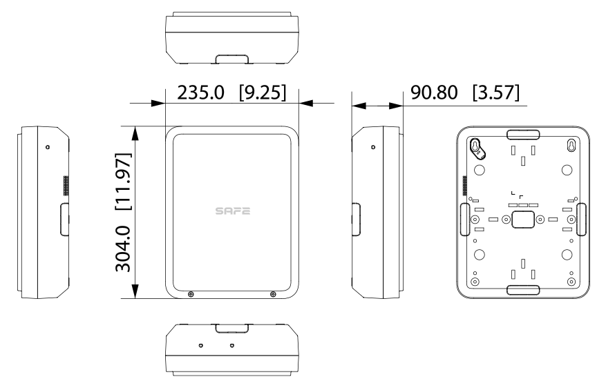
| Product dimensions | 304 × 235 × 90.8 mm |
| Package dimensions | 369 × 140 × 280 mm (L × W × H) |
| Weight | Net 1.22 kg / gross 1.78 kg |
| Installation | On a wall |
| Degree of protection | IP30 |
| Housing material | PC + ABS, white |
| Compatibility | Hub 2 Plus LTE (SAFE 38300) |
| Certification | CE; EN 55032:2015+A1:2020; EN 61000-3-2:2019+A1:2021+A2:2024; EN 61000-3-3:2013+A1:2019+A2:2021; EN 55035:2017+A11:2020; EN 50130-4:2011+A1:2014; IEC 62368-1:2018 / EN IEC 62368-1:2020+A11:2020; EN 301489-1 V2.2.3; EN 301489-3 V2.1.1; EN 300220-1 V3.1.1; EN 300220-2 V3.2.1; EN 62311:2020; EN IEC 63000:2018 |
| Security grade / environmental class | Grade 2 according to ČSN EN 50131 |
| Warranty | 36 months |
Package contents
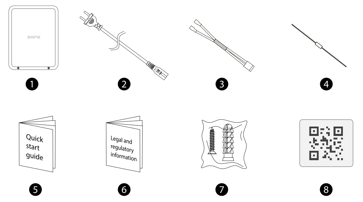
- IO Multi Transmitter module – 1 pc
- Power cable – 1 pc
- Battery cable – 2 pcs
- 2.2 kΩ and 6.8 kΩ resistors – 40 pcs each
- Quick user guide – 1 pc
- Legal and regulatory information – 1 pc
- Mounting kit (screws, wall plugs) – 1 set
- QR code with user manual – 1 pc
Safety notices
- Have the mains power connection made by a qualified electrician in accordance with local regulations.
- Before working on the terminal blocks, disconnect the module from both the mains power supply and the backup battery.
- The module is intended for indoor use only (IP30 protection rating).
- Operate and store the device only within the permitted temperature and humidity range.
- Cable glands must lead into an enclosed, non-flammable space.
- Do not connect the module to more power sources than this manual specifies.
- Do not exceed the load rating of the relay outputs (30 V DC / 3 A) or of the auxiliary power outputs.
- Do not dispose of the product or the battery with general municipal waste – hand them in for recycling in the take-back system.
Warranty
A warranty is provided on the SAFE IO Multi Transmitter device 36 months from the date of sale. The warranty does not cover the backup battery or defects caused by failure to follow the instructions given in this manual.
In case of problems with the device, first contact technical support – most situations can be resolved remotely.
Gallery

Need help?
SAFE HOME europe technical support:
E-mail: info@safe-home.eu · Telephone: (+420) 581 222 262
Web: www.smart-safe.eu