
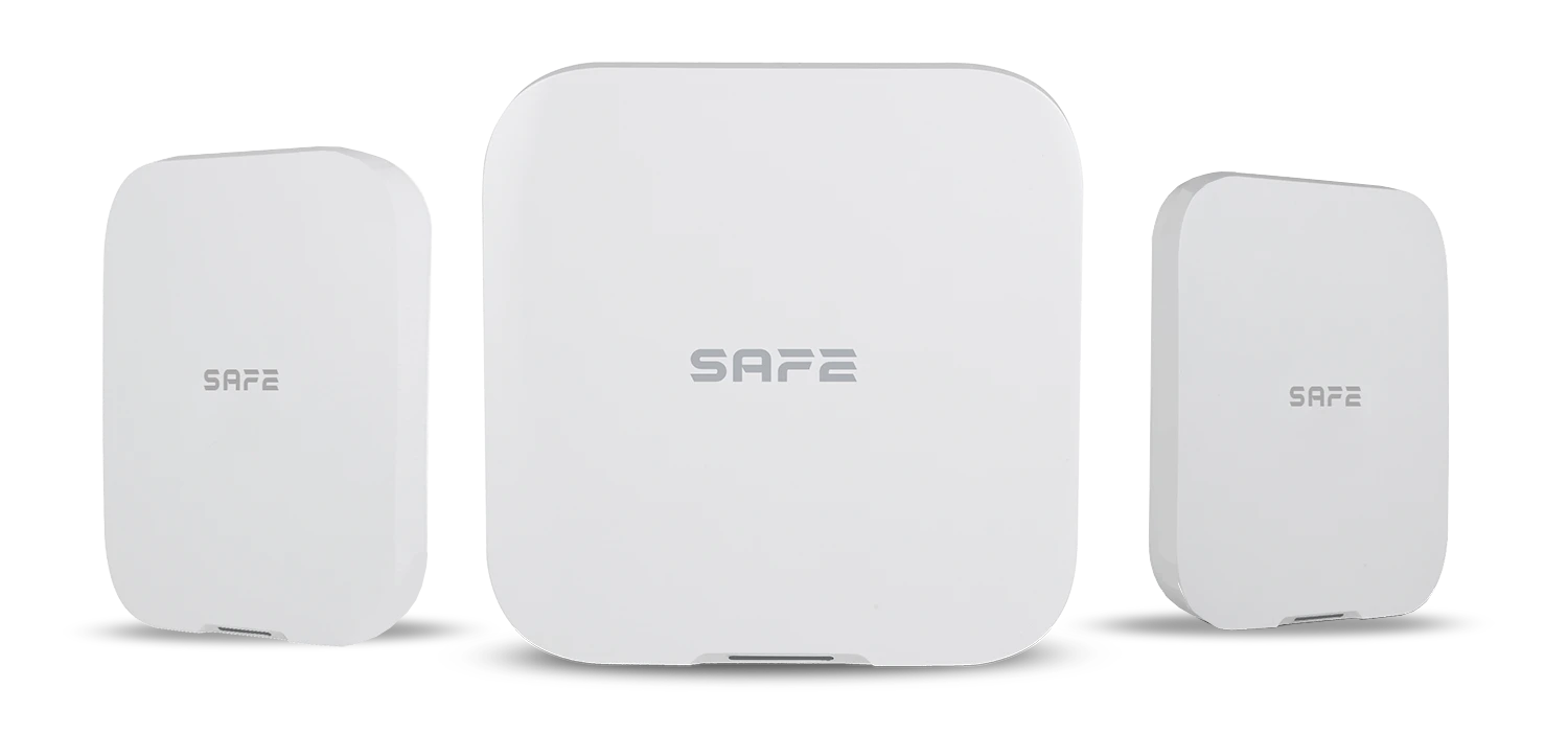
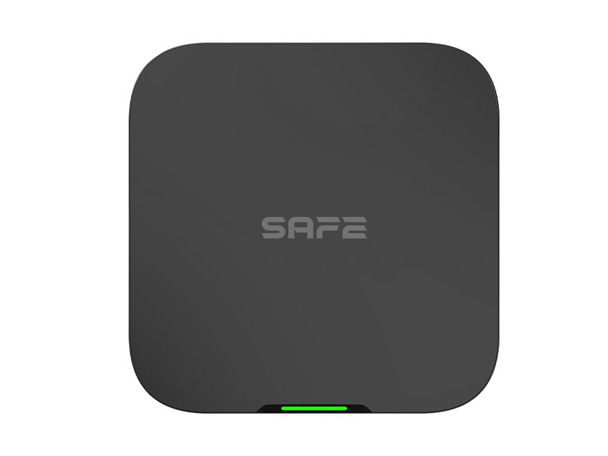
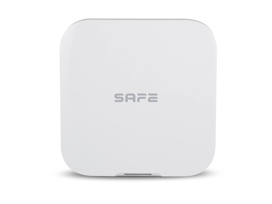
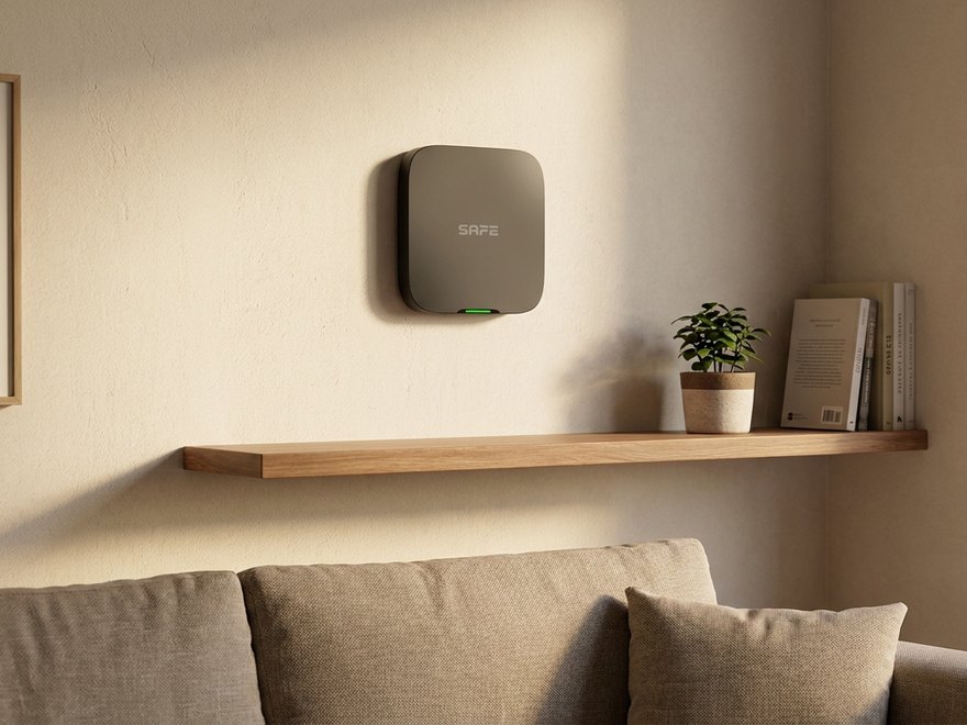
Hub 2 Plus LTE – DC is a hybrid smart SAFE security system Hub operating on low voltage 9–15 V DC, i.e. with no need for mains power. It controls all the devices of the system and alerts users to potential dangers such as a door being forced, a window being broken, intrusion into the secured area, fire hazard or flooding. It supports the connection of up to 150 wireless devices and 64 wired elements. It is suitable for guarding remote properties, building sites, cottages and warehouses as well as for protecting mobile and floating structures where access to the electricity grid is unavailable or problematic. The Hub is certified at Security Grade 2, and thus meets some of the most demanding requirements for resistance to tampering, signal jamming or unauthorised manipulation, while supporting the latest trends in security, such as photo and video verification of alarm events, automation, and integration of IP cameras or third-party systems. It is manufactured in two colour variants (SAFE 38300 white, SAFE 38301 black).
Foreword
General
This user manual describes the installation, functions and operation of the SAFE security system Hub (hereinafter the “Hub”). Read the manual carefully before using the device and keep it for future reference.
Safety instructions
The following signal words may appear in the user manual:
| Signal word | Meaning |
|---|---|
| NEBEZPEČÍ | Indicates a high potential hazard which, if not avoided, may result in death or serious injury. |
| VAROVÁNÍ | Indicates a medium or low potential hazard which, if not avoided, could result in minor or moderate injury. |
| UPOZORNĚNÍ | Indicates a potential risk which could lead to property damage, data loss, reduced performance or an unpredictable result. |
| TIP | Provides methods to help you solve a problem or save time. |
| POZNÁMKA | Provides additional information, such as emphasis or a supplement to the text. |
Revision history
| Version | Revision content | Release date |
|---|---|---|
| V1.0.0 | First release. | August 2026 |
| V1.0.1 | Corrected the power supply information: the Hub has no output for powering other elements (1.2 A is a parameter of the built-in power supply module). Clarified the consumption from the power source and from the battery, and added the power supply of the IO modules. | October 2026 |
| V1.0.2 | Names and order of items in Status and Settings aligned with the ProSAFE app (Weblate translations). | October 2026 |
| V1.0.3 | Added illustrations from the graphic designer. | October 2026 |
| V1.0.4 | Text changes: Functional Elements, Commissioning procedure, Hub status, Hub settings, Area management, Arming and disarming the system, Hub installation, Maintenance, Technical Specifications, Package Contents. | October 2026 |
| V1.0.5 | Text changes: Area management, Arming and disarming the system, Maintenance. | October 2026 |
Privacy notice
As a user of the device or a data controller, you may collect the personal data of others, such as their face, fingerprints and licence plate number. You must comply with local privacy protection laws and regulations in order to protect the legitimate rights and interests of other people by taking measures which include, but are not limited to: providing clear and visible identification to inform people of the existence of the monitored area and providing the required contact information.
About the manual
- The user manual serves as a reference only. Minor differences may occur between the information provided and the product.
- We are not liable for damage resulting from use of the product in a manner that is not in accordance with the instructions in the user manual.
- The manual will be updated in line with the current laws and regulations of the relevant countries. For detailed information, see the printed user manual, scan the QR code or visit our website. The manual is for information purposes only. The electronic and printed versions may differ in minor details.
- All designs and software may be changed without prior written notice. As a result of product updates, certain differences may appear between the product and the information in the manual. The latest version of the software and supplementary documentation is available from customer service.
- Printing errors or deviations may occur in the description of functions, operations and technical data. In case of doubt or dispute, we reserve the right of final interpretation. If the manual (in PDF format) cannot be opened, update your reader software or try another common reader.
- All trademarks, registered trademarks and company names in the manual are the property of their respective owners.
- If any problems occur while using the device, visit our website, or contact your supplier or customer service.
- In case of ambiguity or dispute, we reserve the right of final interpretation.
Important precautions and warnings
This section contains information on the correct handling of the product, risk prevention and prevention of property damage. Read it carefully before using the device and follow the instructions provided while using it.
Operating requirements
- Before use, make sure the device's power supply is working properly.
- Do not unplug the device's power cable while it is switched on.
- Use the device only within its rated power range.
- Transport, use and store the device under the permitted humidity and temperature conditions.
- Prevent liquids from splashing or dripping onto the device. Make sure there are no objects filled with liquid on the device, to prevent liquids from entering it.
- Do not disassemble the device.
Installation requirements
- Before switching on, connect the device to a 9–15 V DC power source.
- Strictly comply with local electrical safety standards and make sure the voltage in the area is stable and matches the device's power requirements.
- Do not connect the device to more than one power source. Otherwise, the device could be damaged.
- When working at height, follow all safety procedures and use the required protective equipment.
- Do not expose the device to direct sunlight or sources of heat.
- Do not install the device in damp, dusty or smoky locations.
- Install the device in a well-ventilated location and do not block its ventilation.
- Use the power adapter or power supply provided by the device manufacturer.
- The power supply must meet the ES1 requirements of IEC 62368-1 and must not exceed PS2. The power supply requirements are governed by the device's rating label.
- Connect Class I electrical appliances to a socket with protective earthing.
Functional elements
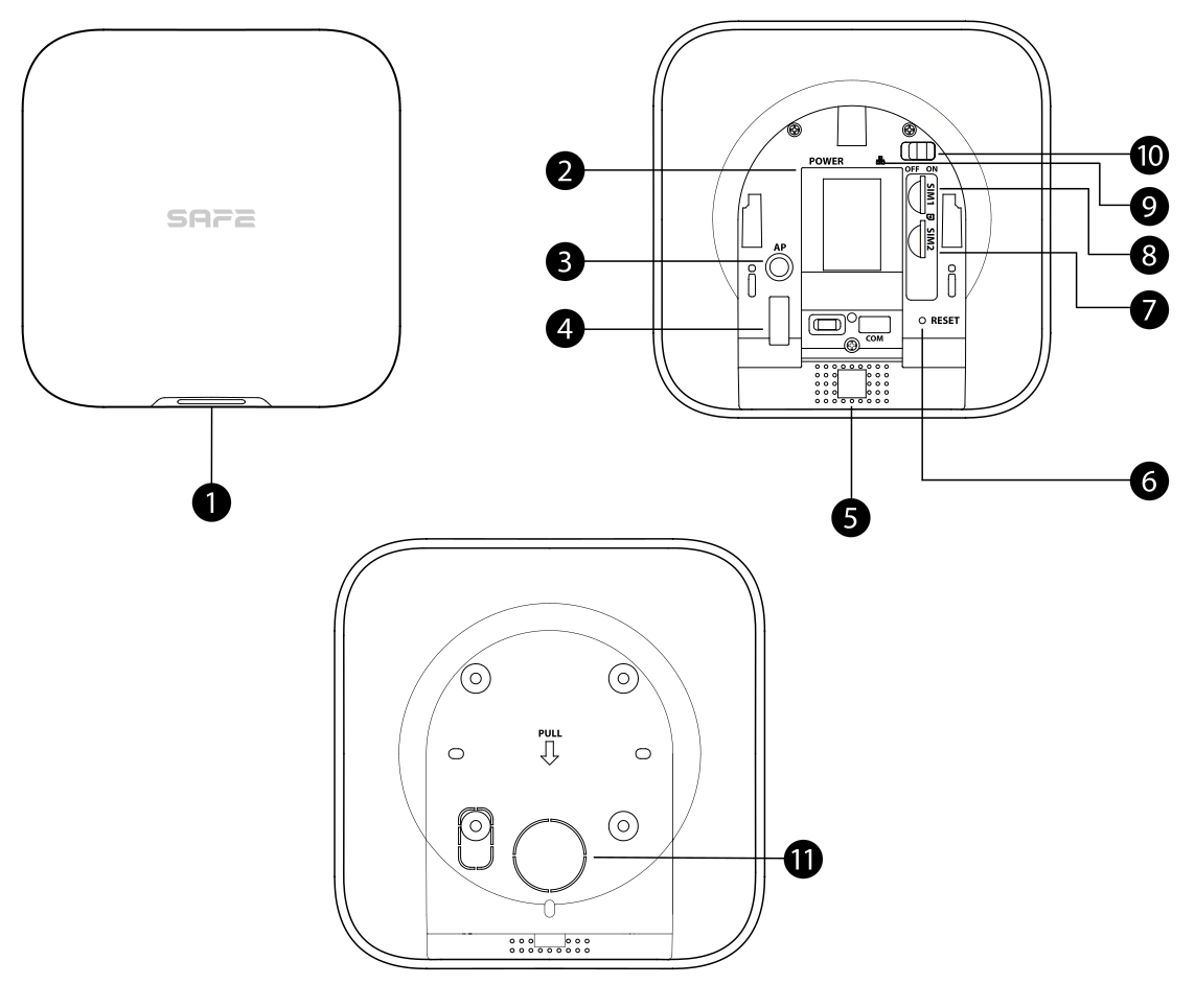
- Indicator — signals the Hub status in the following ways:
- Slowly flashes green: reduced sensitivity mode.
- Flashes green: the Hub is starting up.
- Lights up yellow: failed to connect to the cloud.
- Lights up green: Disarmed status.
- Lights up blue: Armed status.
- Flashes red: an alarm event has been triggered.
- Flashes yellow: a fault has been detected.
- Flashes blue: AP configuration or pairing of the Hub with devices is in progress.
- Flashes blue rapidly: card issuing mode.
- Power connector — used to connect the power supply.
- AP button — press and hold the button for 2 seconds to turn on the AP function; the phone then connects to the hotspot broadcast by the Hub, and the Wi-Fi network login credentials (username and password) are synchronised to the Hub. The AP function can be turned off the same way — press and hold the button for 2 seconds while AP is on.
- Tamper contact — when the tamper contact is released, a tamper alarm is triggered.
- Speaker — used to emit sound.
- Reset button — press and hold the button for 10 seconds to restart the Hub and restore factory settings.
- SIM 2 slot — install the primary card in the first slot and the backup card in the second slot.
- Two SIM cards are supported, one of which is a backup (dual SIM, single standby).
- SIM cards allow the Hub to use mobile data and send push notifications about alarms.
SIM cards will not work until the network configuration is completed.
The SIM function is available only on selected models.
- SIM 1 slot — slot for installing the primary SIM card; see item 7 above for description.
- Ethernet cable connector — used to connect the Hub to the Ethernet network.
- Power switch — used to turn the Hub on or off.
- Rear cover — when the rear cover is opened, a tamper alarm is triggered.
Dimensions
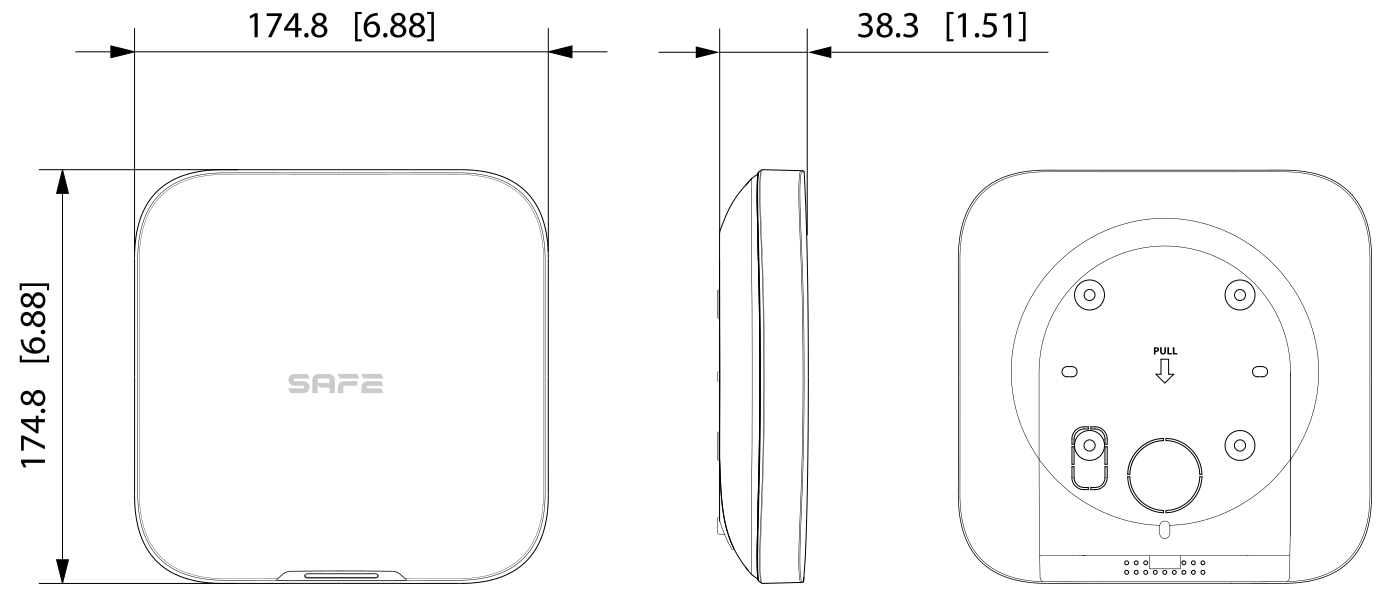
The Hub's dimensions are shown in the figure below (unit: mm [in]).
Principle of operation
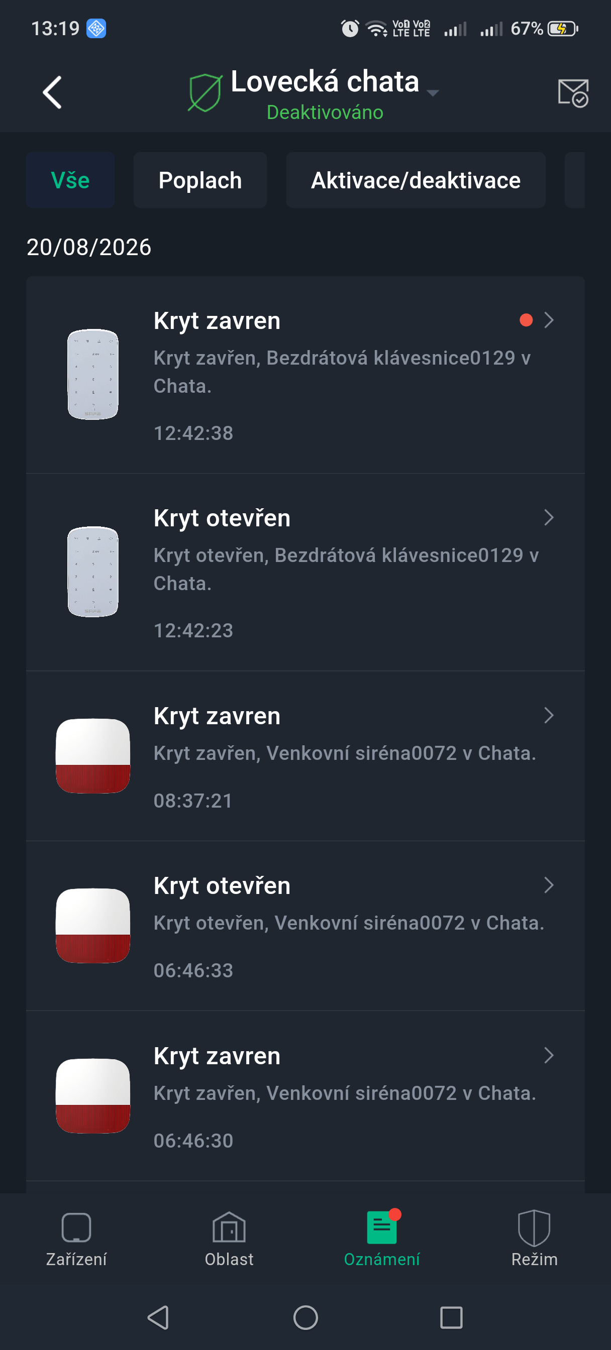
The Hub collects information about the activity of connected devices in encrypted form and analyses it. If the system detects an intrusion or other danger in an armed area, the Hub instantly:
- alerts the user in the app ProSAFE (push notification, SMS, phone call),
- sends an alarm message to DPPC (monitoring and alarm receiving centre) using the SIA or SoftGuard protocol,
- for devices with a camera, sends images for visual verification of the alarm.
Four communication channels
The Hub can be connected to the internet via Ethernet, Wi-Fi a the LTE mobile network with two SIM cards (primary + backup; only one is active at a time). If one channel fails, the system automatically continues via the next available one — connectivity thus remains maintained even if the Ethernet cable is disconnected or Wi-Fi fails.
SAFE Keeper protocol
Communication between the Hub and devices is provided by an encrypted bidirectional radio protocol SAFE Keeper (868.0–868.6 MHz):
- AES-128 encryption with a rolling code and authentication of connected devices,
- range up to 2 000 m in open space,
- when jamming is detected, the system alerts the user and automatically switches to an unjammed frequency band,
- regular connection checks — the system immediately reports a device dropout.
Expansion with wired components
Hub 2 Plus LTE features an integrated port RS-232 for connecting Serial Bridge (SAFE 38181), which forms a communication bridge for connecting wired devices via the integration modules IO Expander Board (SAFE 38182) a IO Relay Board (SAFE 38183). Thanks to the SAFE system, you are therefore not limited to the options of a wireless solution only — you can further expand the system with wired elements as your needs grow.
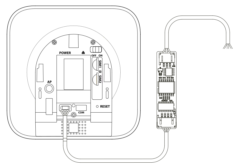
The Serial Bridge is powered directly from the Hub's port. The IO Expander Board and IO Relay Board modules have their own 12 V DC power supply (power consumption 1.2 W / 1.8 W per module) – the Hub does not power them.
The modules make it possible to modernise existing installations without having to replace functional equipment. You simply connect older security elements to the SAFE platform and gain management via the ProSAFE app, automation scenes and detailed notifications on your smartphone, all without any complicated additional programming.
Sabotage protection
The SAFE system cannot be taken out of operation without the user's knowledge. The Hub alerts the user to device failure or loss of connection and stores events in a log (up to 5,000 records). In the event of a power outage, it continues operating from the backup battery for up to 12 hours; the offline cache retains up to 50 alarm messages.
Photo verification of alarms
The Hub works with Motion Cam detectors (indoor and outdoor) with a photo verification function — it sends images from the detectors immediately to the ProSAFE app or to the DPPC. Up to 8 IP cameras can also be connected to the system for sending video during an alarm.
Cloud update
The firmware of the Hub and of connected devices is updated remotely from the cloud — automatically, or after user confirmation. A dual firmware backup system ensures automatic recovery if an update fails.
Users and roles
Users can only be created in the ProSAFE app. Assign roles to users so that they have different levels of access to device control.
| Role | Access level | Description and permissions |
|---|---|---|
| Owner | L2 | The user who initialises the device (adds it to the ProSAFE app) becomes the Owner. Only the Owner can share the device with other users – no one else can do this, not even an Administrator. This role cannot be changed or transferred. While a technician has borrowed the Hub from the user, or the Owner has entrusted it to the technician, the Owner does not have permission to configure the device. |
| Administrator | L2 | Can do everything except share the device – device configuration and user management, including setting their permissions. |
| User | L2 | Can only operate the system (arming and disarming areas); cannot manage device settings or users. |
| Installer | L3 | Technicians provide operation and maintenance services to end users. This role must obtain access to the device by requesting permission from the end user (the Owner). The technician may be granted permissions, for example to configure the device and manage users. |
Commissioning procedure
Commission the wireless alarm system according to the following procedures.
End user
- Add the Hub in the ProSAFE app. This makes you the Owner of the system with all the relevant permissions.
- Next, choose one of the following procedures:
- Share the device with other ProSAFE users.
- Entrust the device to an Installer – the technician must approve your entrusting request.
- Once the technician approves the entrusting, you can at any time:
- change their permissions,
- cancel the entrusting of the device to the technician,
- extend the entrusting period.
- Arm and disarm the system using the keypad, key fob or the ProSAFE app. After sending the arm command, the ProSAFE app checks the system status. If the system reports a fault, you choose whether to arm it anyway (Forced Arming).
Details for individual devices can be found in the operating manual of the respective device.
Installer
- Connect the Hub to the Ethernet network and turn it on.
- Add the Hub to the ProSAFE app and add devices to the Hub.
- Install the Hub on a wall. We recommend using wall plugs. Do not place the Hub:
- outdoors,
- near metal objects that attenuate and shield the radio signal,
- in places with a weak GSM signal,
- near sources of radio interference, at a distance of less than 1 metre from the router and power cables,
- in places where the temperature and humidity exceed the permitted limits.
The installation set contains: the Hub, countersunk screws M3 × 8 mm, self-tapping screws ST4 × 25 mm, a mounting plate and wall plugs.Installation procedure:- Hold the mounting plate against the wall, mark the positions of the mounting holes and drill the holes.
- Insert the wall plugs into the holes.
- Hold the mounting plate against the wall and align the holes in the plate with the wall plugs.
- Secure the mounting plate with the ST4 × 25 mm self-tapping screws.
- Fit the Hub onto the mounting plate from top to bottom.
- Secure the Hub to the mounting plate with the M3 × 8 mm countersunk screws.
- Configure the Hub in the ProSAFE app.
- You can gain access to the device in one of the following ways:
- add the device as the Owner,
- request permission from the Owner – the Owner approves your request,
- accept the Owner's request to entrust the device,
- borrow the device as a technician (ProSAFE).
- Perform device operation and maintenance.
- The procedure ends when the Owner cancels the entrusting of the device, or when you, as the technician, end the device loan.
ProSAFE account
The security system is configured and controlled through the ProSAFE app. The ProSAFE app is available for both iOS and Android. This chapter describes the procedure on iOS.
Prerequisite: you have the latest version of the app installed.
Registration
- Search for ProSAFE in the App Store and download the app.
Android users can download the ProSAFE app from Google Play.
- On your phone, click the app icon to launch it.
- Create an account.
- Click Register.
- Select your country or region from the list.
- Enter your email address and password for registration.
Click the eye icon to show the password; the icon then changes to a crossed-out eye.
- Tick the box to agree to the ProSAFE registration terms and conditions, the Privacy Policy and the Smart-safe Pass Privacy Policy.
- Click Get verification code, check your mailbox and enter the code you receive.
Use the verification code within 60 seconds of receiving it, otherwise it will expire.
- Click OK.
Login
- Return to the login screen, enter your email address and password and click Log in.
Adding the Hub to the app
- On the Devices screen, click the + icon and select Scan QR code.
- Add the device.
- Scan the QR code directly on the device, or click the gallery icon and import an image with the QR code.
- Click Enter SN manually and enter the device's serial number to add it manually.
- Select the device type and click Next.
If the system recognises the device type automatically, click Next straight away.
- On the Add device screen, edit the device name, enter the device's username and password and click Save.
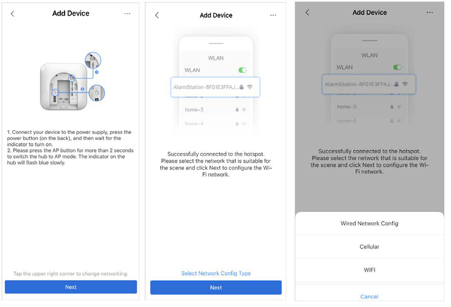
- Configure the network settings.
- On the Add device screen, click Next and connect to the Hub's hotspot.
- Once the connection has been established successfully, click Select network configuration type.
- Select the network types you want to configure.
- Ethernet: enable DHCP, or enter the IP address, subnet mask, gateway, DNS and MAC address manually.
- Cellular: configure the APN, authentication mode, username, password, dial number and data roaming for the SIM card.
- Wi-Fi: select the Wi-Fi network and enter its password to connect to it.
Adding devices to the Hub
You can add multiple devices to the Hub. For details on adding each type of device, see the user manuals of the respective devices.
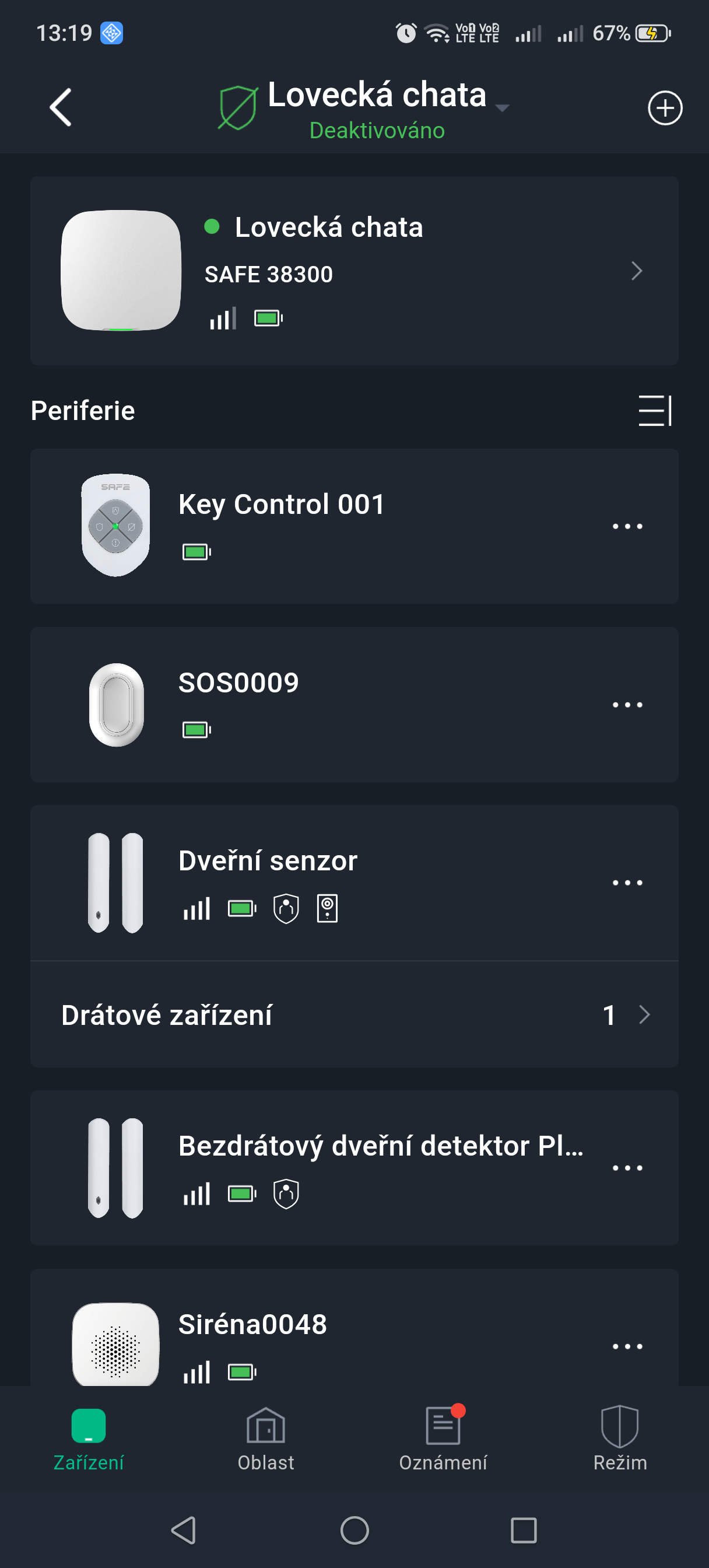
On the Hub's Devices screen, click the + icon and select Add device.
Adding a device
Adding one at a time:
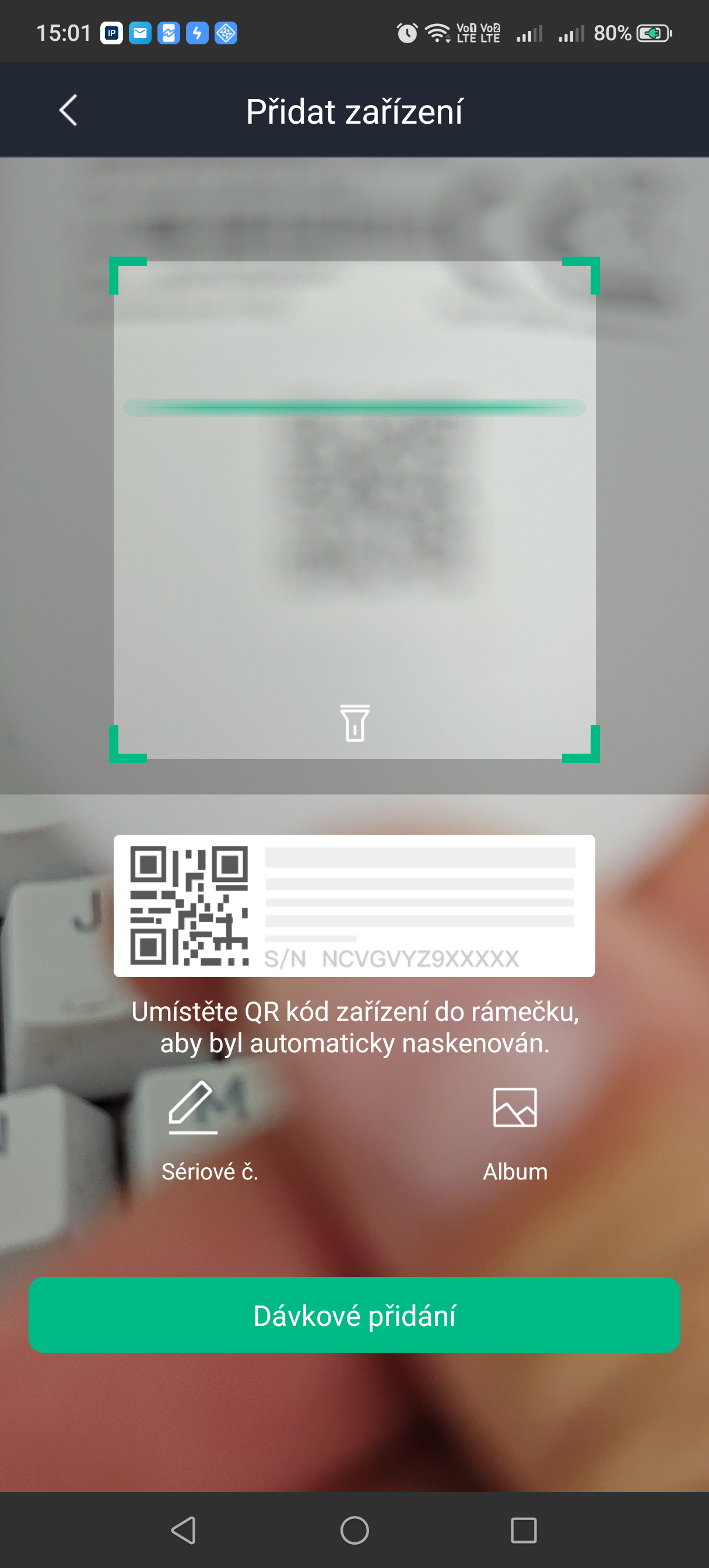
- Scan the QR code on the underside of the device and click Next.
You can also enter the device's serial number manually by clicking SN, or select an image of the QR code from My files.
- Follow the on-screen instructions to switch on the device and click Next.
- Wait for the pairing to complete.
- Enter the device name, select an area and click Done.
Batch adding
Click Batch adding and then Start to begin pairing.
Switch on the device. If the indicator on the device flashes green quickly and then goes out, pairing was successful. Repeat this procedure, adding devices one at a time.
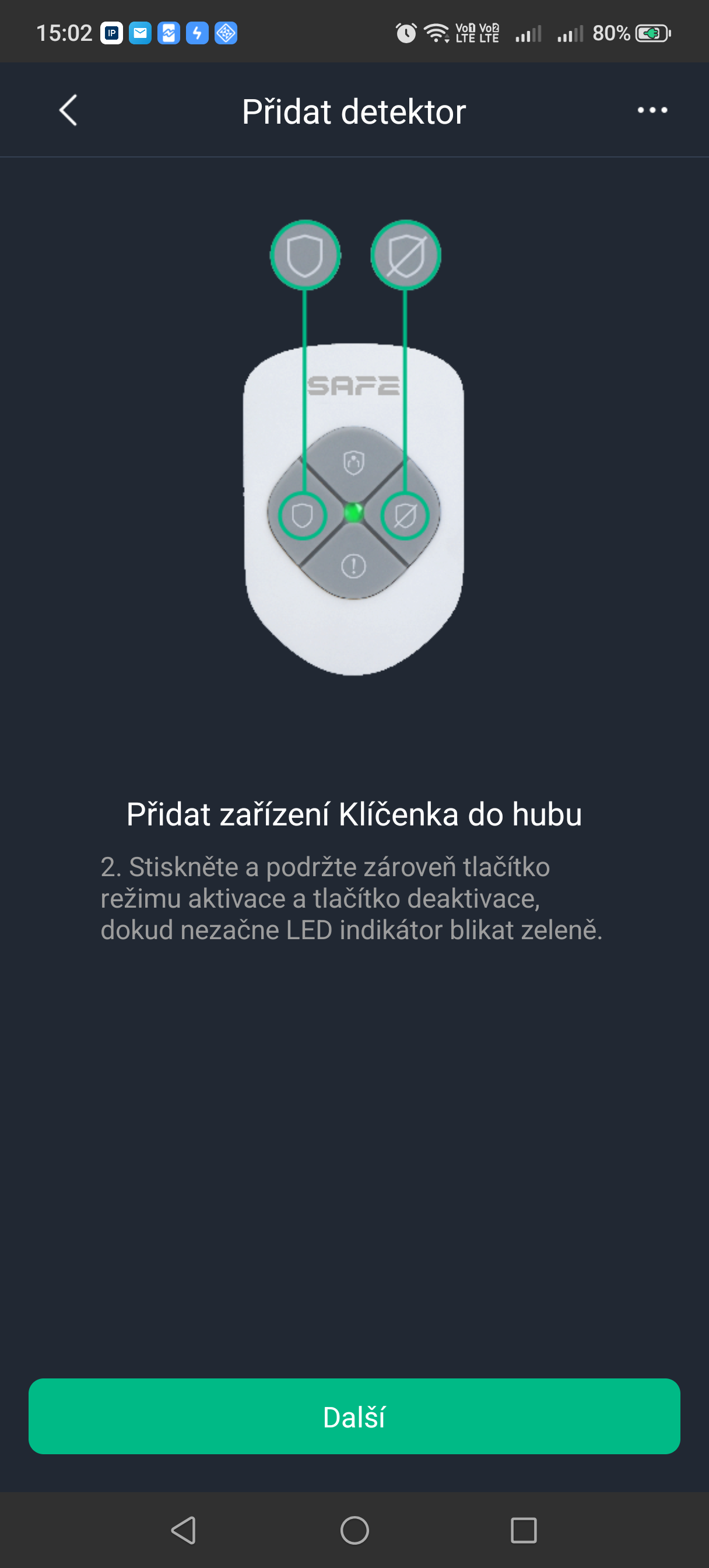
For controllers (key fobs), start pairing by pressing the Arm and Disarm buttons at the same time. For panic buttons, enter pairing mode by holding the button for 8 seconds.
Adding an IP camera
Add an IP camera (IPC) to the Hub.
- On the Hub's Devices screen, click the + icon and select Add IP camera.
- Add the IP camera to the Hub.
- Manual adding:
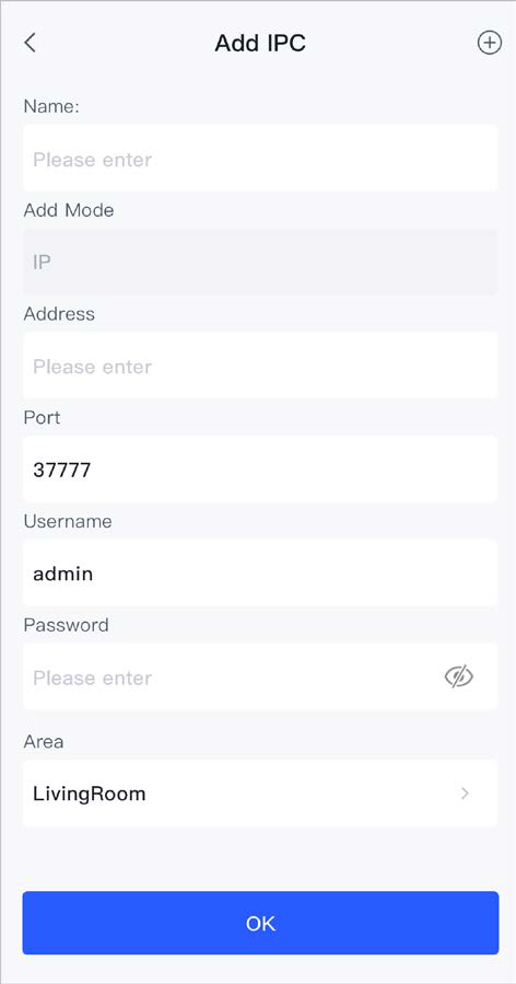
- Enter the device name, the IP camera's IP address, port number, and the IP camera's username and password, select the area to which the IP camera is assigned and click OK.
- Select the IP camera channel and click OK.
- Online search:
- Click the menu icon and select Search in LAN to search for IP cameras in the same network segment.
- Click Next.
- Enter the IP camera's password, select the area to which the IP camera is assigned and click OK.
- Select the IP camera channel and click OK.
- Manual adding:
Related procedure
For an added IP camera, you can configure its parameters.
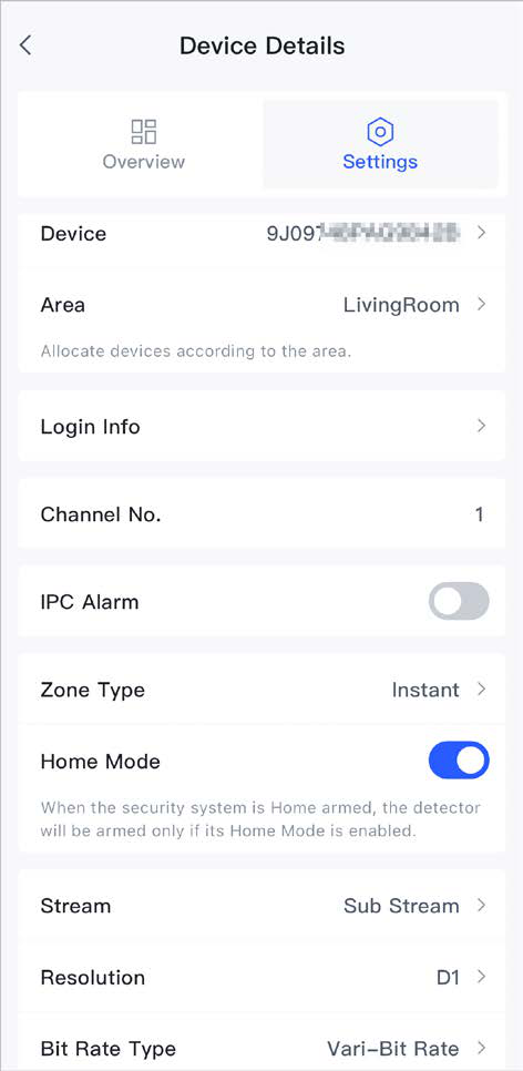
- For the IP camera in question, select Device Details.
- Select Settings and configure the IP camera's parameters.
Adding an expansion module
- On the Hub's Devices screen, click the + icon and select Add expansion module.
- Click Start to add the expansion module.
Check that the expansion module's RS-485 bus is connected to the Hub, set a unique address on the module using the DIP switch and then switch the module on.
Video linkage to alarm
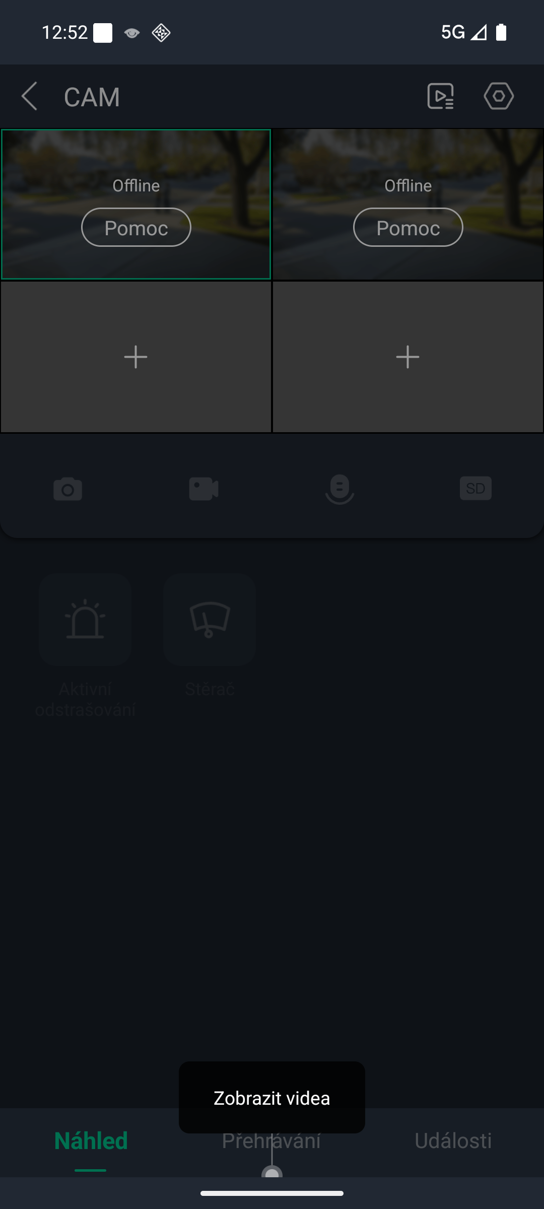
Configure video linkage to alarm for a device so that you can view the video recording if an alarm is triggered.
Prerequisites
- Before configuring video linkage to alarm, the Hub must be armed.
- Devices must have been added to the Hub.
- On the Hub's Devices screen, select the device and go to Device Details > Settings to configure the parameters.
- Turn on Video linkage to alarm and select the Video channel.
- From the Linked channel list, select a video channel and tap Save.
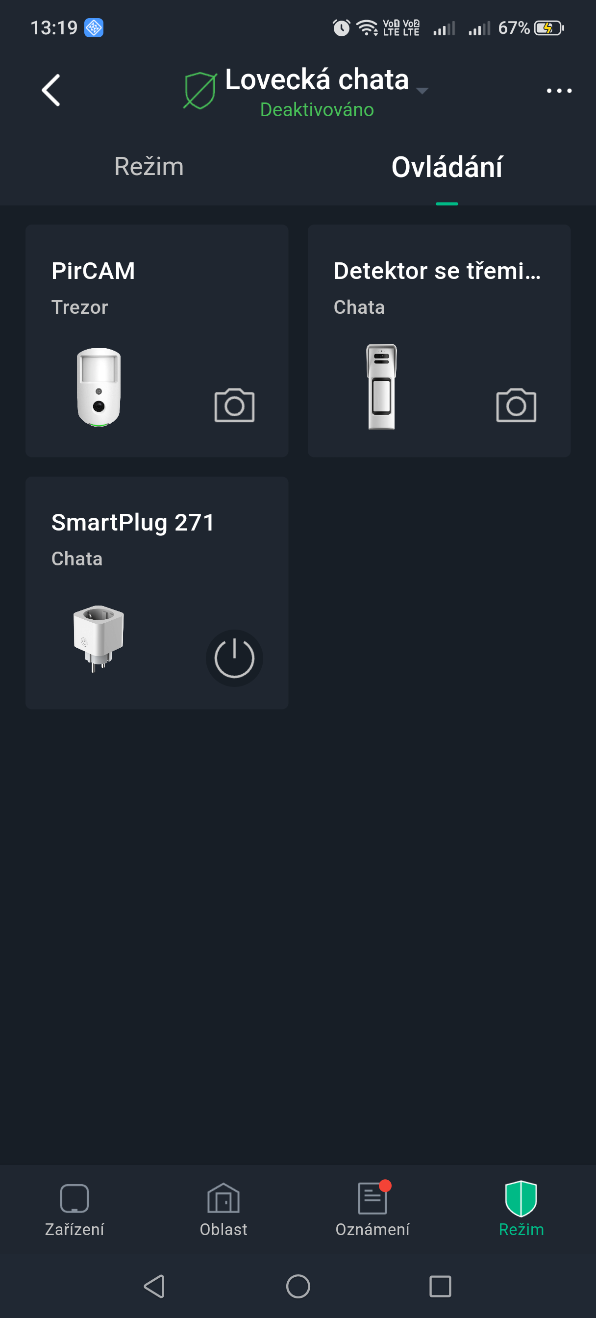
Hub status
Hub icons
In the ProSAFE app, the following icons are shown on the Hub display with the meanings below:
| Parameter | Meaning |
|---|---|
| LTE signal strength | States: very weak, weak, good, excellent, no signal. |
| Wi-Fi signal strength | States: very weak, weak, good, excellent, no signal. |
| SIM card | States: SIM card 1 active, SIM card 2 active, no SIM card, SIM card unlocked, SIM card locked. |
| Battery Level | Shows the charge level in steps: 100%, 80%, 60%, 40%, 20%. |
Hub overview and status
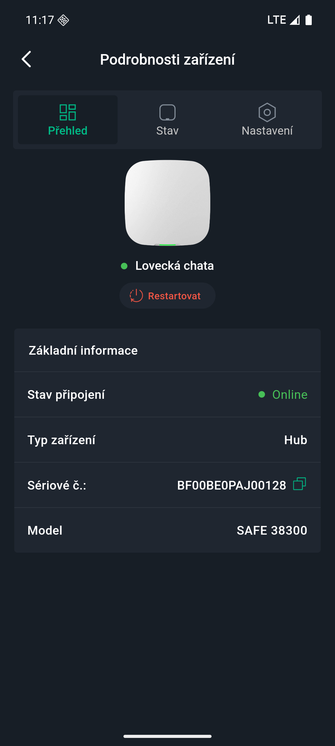
On the Devices screen in the ProSAFE app, select the Hub and then the Overview or Status tab to view information and the status of the Hub.
Overview
| Parameter | Meaning |
|---|---|
| Basic information | Shows basic information about the Hub. |
| Online status | Shows the connection status of the Hub (online/offline). |
| Type | Shows the device type. |
| SN | Shows the serial number of the Hub. |
| Model | Shows the Hub model. |
Status
| Parameter | Meaning |
|---|---|
| LTE signal strength | Mobile network signal strength for the active SIM card. |
| Wi-Fi signal strength | Status of the Hub's internet connection via Wi-Fi. For greater reliability, we recommend installing the Hub in a location with a signal strength of at least 2 bars. |
| Battery Level | Shows the remaining battery capacity as a percentage. |
| Tamper | Shows the tamper protection status of the Hub (against opening). States: opened, closed. |
| External power | Shows the connection status of the external power supply. States: connected, disconnected. |
| GSM | Shows the GSM connection status of the Hub. States: connected, disconnected. |
| Wi-Fi | Shows the Wi-Fi connection status of the Hub. States: connected, disconnected. |
| Ethernet | Shows the Ethernet connection status of the Hub. States: connected, disconnected. |
| SIM card | Shows the SIM card connection status. States: SIM 1, SIM 2, none, locked (this state is shown only if a SIM card is inserted in the Hub). |
| DPPC1 – primary / DPPC1 – secondary / DPPC2 – primary / DPPC2 – secondary | Shows the connection status to monitoring and alarm receiving centres (DPPC) 1 and 2. States: connected, disconnected. |
| Firmware version | Software (firmware) version of the Hub. |
Hub settings
General settings
On the Hub screen, tap Settings — the device details are displayed.
| Parameter | Description |
|---|---|
| Device | Shows the name, type, serial number and model of the Hub; edit the device name (confirm by tapping Save). |
| Hub settings | Configuration of Hub parameters (see the table below). |
| Network | Shows current information about the network connection. |
| Time zone | Select the time zone in which the Hub operates; optionally daylight saving time (DST) – select the date or the week and time of the start and end. |
| Language | Language of voice announcements and SMS. 18 languages are supported: Arabic, Czech, Danish, Dutch, English, French, German, Italian, Portuguese, Russian, Spanish (LA and EU), Turkish, Slovak, Polish, Greek, Bulgarian, Estonian. The default is English. |
| User manual | Opens the user manual of the Hub. |
| Firmware update | Online (cloud) update. |
On the Devices screen in the ProSAFE app, select the Hub and then tap Settings > Hub Setting to view and edit the general information about the Hub.
| Settings | Description |
|---|---|
| Back up configuration | If the Hub is damaged, you can transfer its parameters and device configuration to another Hub. Once this function is enabled, the Hub configuration is backed up regularly. |
| User management | Allows you to add, edit or delete app or keypad users, only in the Disarmed state.
|
| SOS Alarm | Configuration of SOS alarm types: panic alarm, siren linkage, medical alarm and fire alarm. Once configuration is complete, you trigger the alarm by tapping SOS on the Hub Operation screen. If more than one alarm type is selected, a pop-up window appears asking which alarm is to be triggered this time. |
| Installer | Entrusting to a service provider. Tap Entrust, enter the service provider's account and the entrusting period, select the devices to be entrusted, tick I have read and agree to the User Agreement and tap Next. |
| Global arming/disarming | Arm or disarm all devices in all areas with a single tap. |
| Scheduled arming/disarming | Arm or disarm areas according to a time schedule.
|
| Sound settings |
|
| LED indicator | LED indication is enabled by default.
If LED indication is disabled, the indicator remains off regardless of whether the Hub is operating normally or not.
|
| Intercom service | Enabling the Intercom service function activates the intercom.
|
| Phone number management |
|
| Test Mode | Tap Start to test the status of the devices connected to the Hub in the individual areas; tap Stop to end the test. |
| Reduced sensitivity mode | When reduced sensitivity mode is enabled, the transmission power of the Hub is reduced. |
| Import configuration | Allows you to transfer the configuration from one Hub to another Hub of the same model. After the import, existing entrusting, lending and security service relationships are not retained. Proceed with caution.
Before importing a configuration, you must enable the Configuration backup function.
|
| Cloud service connection | Set the ping interval between the server and the Hub in the range of 150 to 900 seconds (default 150 seconds). If D-cloud detects that the Hub has been disconnected for longer than 150 seconds, it reports the Hub status to the user via the app. |
| Heartbeat | Setting of the ping interval between the Hub and the devices. This setting determines how often the Hub communicates with the devices and how quickly a loss of connection is detected.
|
| Tamper siren linkage |
|
| System integrity check | When enabled, the Hub checks during arming whether the current state of the system is in order. If an anomaly is detected, it prevents arming. The following items are checked: arming despite reported faults, main power failure, main power failure delay, Hub tamper, connection to the cloud platform, Ethernet error, Wi-Fi error, mobile network error, radio frequency jamming and connection to the DPPC.
|
| DPPC | Enter the IP address/domain, port and device ID and register the Hub on the SAFEWatch / SAFEWatch Pro platform or on a converter (Converter). |
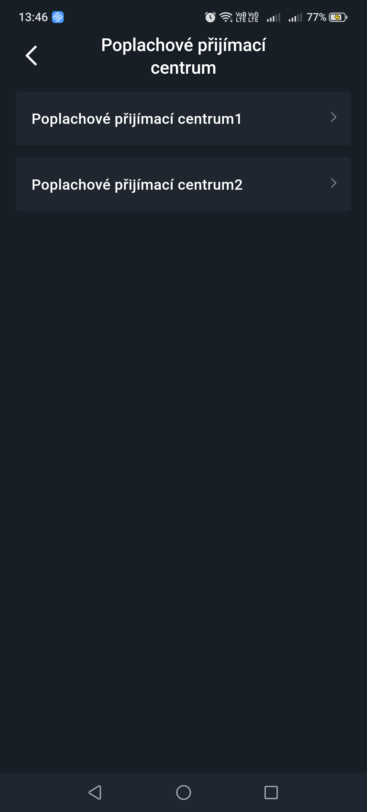
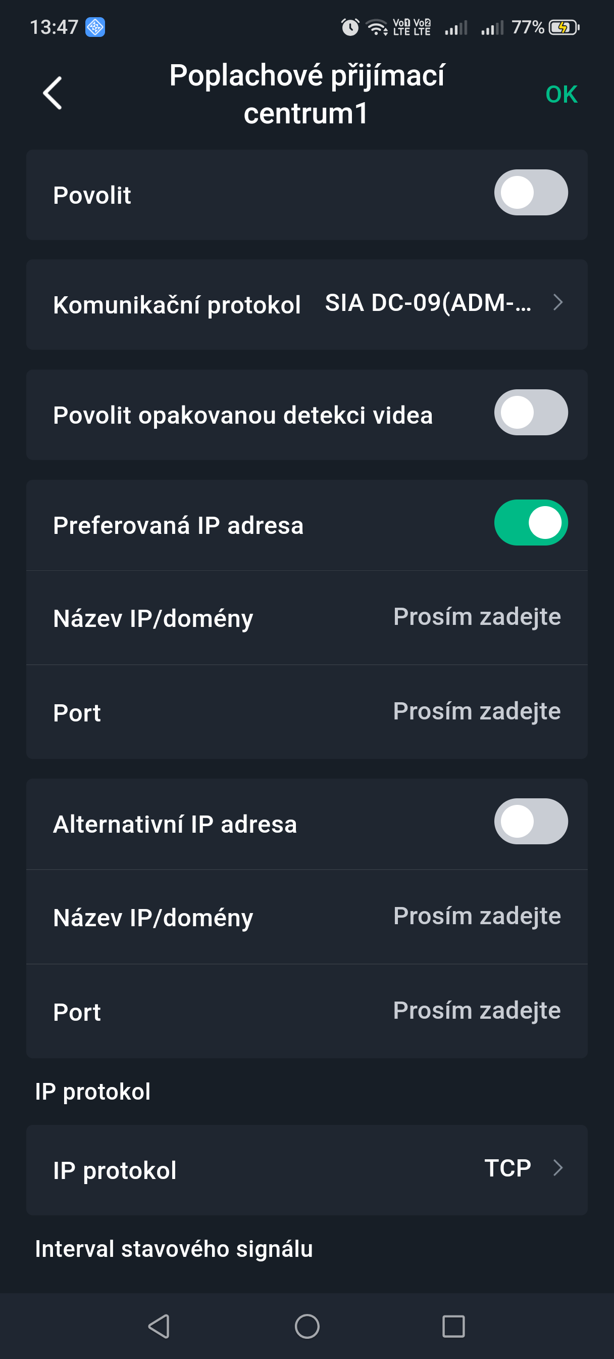
| Monitoring and alarm receiving centre (DPPC) | Select DPPC 1 or DPPC 2 and go to the relevant configuration screen. Enable the function and set the parameters.
SP2: LAN/WIFI via CLOUD, ProSAFE app (default reporting time 150 s) or DPPC reporting time min. 25 h.
DP2: primarily LAN/WIFI via CLOUD, ProSAFE app (default reporting time 150 s) or DPPC reporting time min. 30 min, secondarily GPRS/4G via CLOUD, ProSAFE app (default reporting time 150 s) or DPPC reporting time min. 30 min. |
Network configuration
On the General configuration screen in the device details, tap Network configuration. You can then select the network type for the Hub: wired network, Wi-Fi or mobile network.
Ethernet
- Select Network Setting > Ethernet configuration.
- Set the parameters of the wired network connection.
| Parameter | Description |
|---|---|
| DHCP | If a DHCP server is available on the network, you can enable DHCP – the Hub then obtains a dynamic IP address automatically. |
| IP address, subnet mask, gateway, DNS, DNS 2, MAC address | Manual setting: set the IP address, subnet mask, default gateway, DNS and MAC address manually for the Hub. |
Wi-Fi
- Select Network Setting > Wi-Fi configuration.
- Select an available Wi-Fi network in range and enter the network password to connect.
Mobile network
- Select Network Setting > Mobile network.
- Set the mobile network parameters.
| Parameter | Description |
|---|---|
| Mobile network | Tap the switch next to Mobile network to enable the mobile connection. |
| Priority | Tap the switch next to Priority to set the mobile network as the priority choice when selecting a network. |
| SIM 1 / SIM 2 | Two SIM cards are supported in single standby mode. The SIM cards enable the Hub to use mobile data and send push alarm notifications. |
| APN | Access Point Name (APN) is the name of the setting that the device uses to establish a connection (gateway) between the operator's mobile network and the public internet. |
| Authentication mode (Auth Mode) | Authentication mode of the mobile connection. |
| User name / Password | User name and password for the mobile network. |
| Dial Number | The number to which the Hub is to connect (dial). |
| Roaming data | Enable the function if you are travelling outside the coverage of your home network and need internet access. |
| Mobile data usage | Shows mobile data usage statistics. |
| Reset statistics | Resets the mobile data usage statistics and starts counting again from the beginning. |
| PIN | Allows you to enter the PIN codes of SIM 1 and SIM 2 separately, if required for protection. |
Device management
The administrator (ProSAFE user) can add installers by entrusting devices to them. Devices can be entrusted to an installer individually or in bulk.
Entrusting a device to an installer
Entrusting devices in bulk
You can entrust devices in bulk to the Smart-safe Care service (installer).
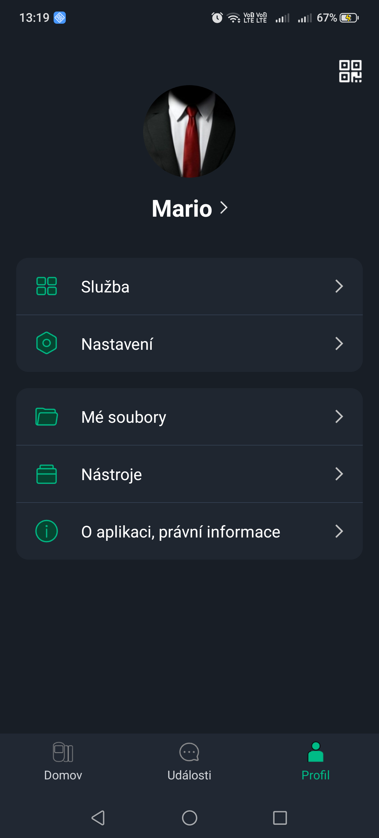
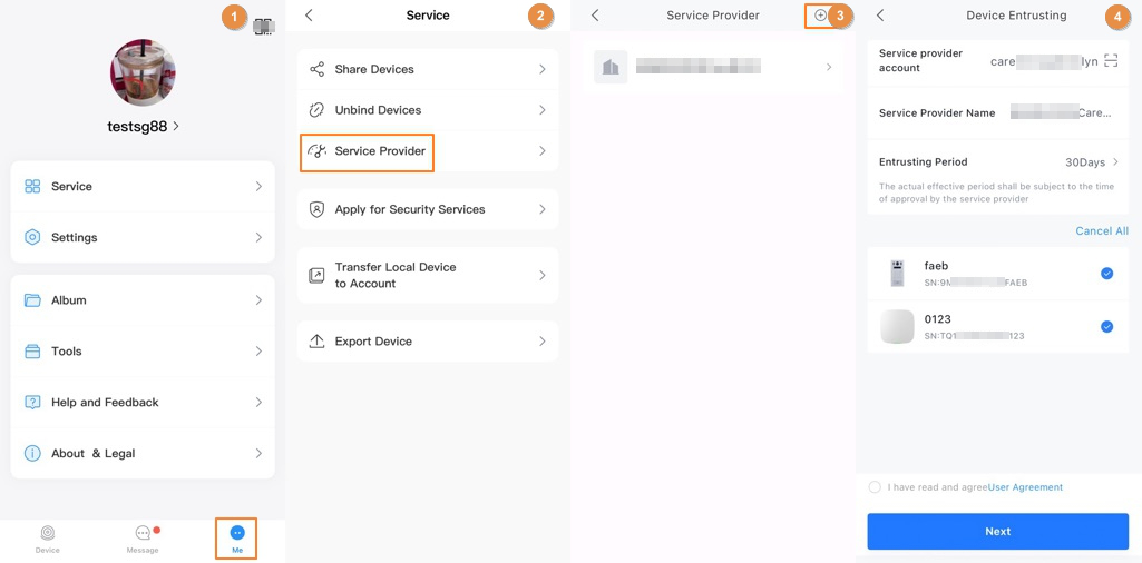
- On the Devices screen, select Me > Services > Service Provider and tap the relevant icon.
- On the Entrusting screen, confirm the details of the linked service provider, or tap the icon to scan the QR code of the service provider.
- Select the devices you want to entrust and entrust them to the Smart-safe Care service. The procedure for entrusting several devices is the same as for entrusting a single device.
Entrusting devices individually
You can entrust a device to an installer (service provider user) individually and set the entrusting permissions at the same time.
- On the Devices screen, tap the icon next to the relevant device and then tap Entrust device.
- On the Entrusting screen, confirm the details of the linked service provider, or tap the icon to scan the QR code of the relevant installer.
- Select the entrusting period and permissions and tap OK.
| Permission | Description | Note |
|---|---|---|
| Health Management | Selected by default; it cannot be cleared. Includes permission for a one-tap health check, error reporting, error fixing, data statistics and the health report. | — |
| Video device | You can request permission for device configuration, live video and playback of recordings.
|
You can choose a temporary permission, for example for 1 hour or 4 hours, or choose authorisation for the whole duration of the entrusting. For example, if the entrusting period is 30 days, you will have the given permission for the whole 30 days. |
| Alarm devices | You can request permission for device configuration and control.
|
|
| Video intercom devices | You can request permission for device configuration and control.
|
- Read and tick I have read and agree to the User Agreement, then tap Next.
The entrusting status can be viewed on the device list screen. After successful entrusting, the device status changes from Under Reviewing through Entrusting to the name of the installer/service provider.
Related operations
- Changing permissions: go to the Entrusted to company screen and tap Change permissions.
- Revoking entrusting: go to the Entrusted to company screen and tap Revoke.
- Extending the entrusting period: go to the Entrusted to company screen and tap Extend.
Sharing devices
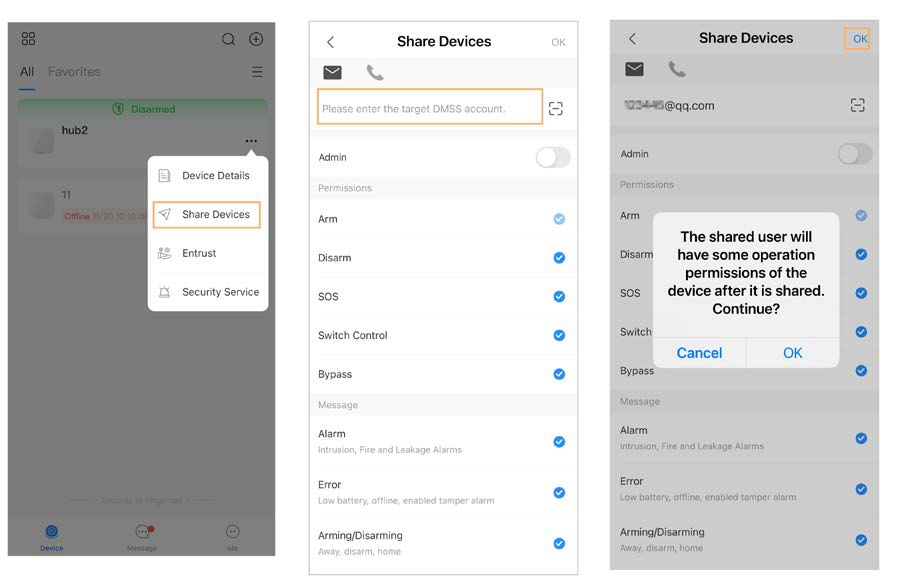
- On the Devices screen, tap the icon next to the relevant device and then tap Share device.
- On the Device sharing screen, share the device with a user by entering their ProSAFE account or scanning their QR code.
- Select the device permissions for the user according to actual need.
- Click OK.
The account with which the device was shared is displayed in the Shared users section on the Device sharing screen.
Unbinding a device
If, when adding a device, you find that it is already paired with another account, you can first cancel the pairing and then add the device successfully.
- Select Me > Services > Unbind device.
- Scan the QR code or enter the serial number (SN) of the device manually. There are 2 ways to do this:
- Unbind request: the system displays an authorisation code – upload the required images following the on-screen instructions. The system then verifies the submitted data; once verification is successful, the device can be unpaired.
- Unbinding with the device password: if you know the device password, enter it to cancel the pairing of the device.
Area management
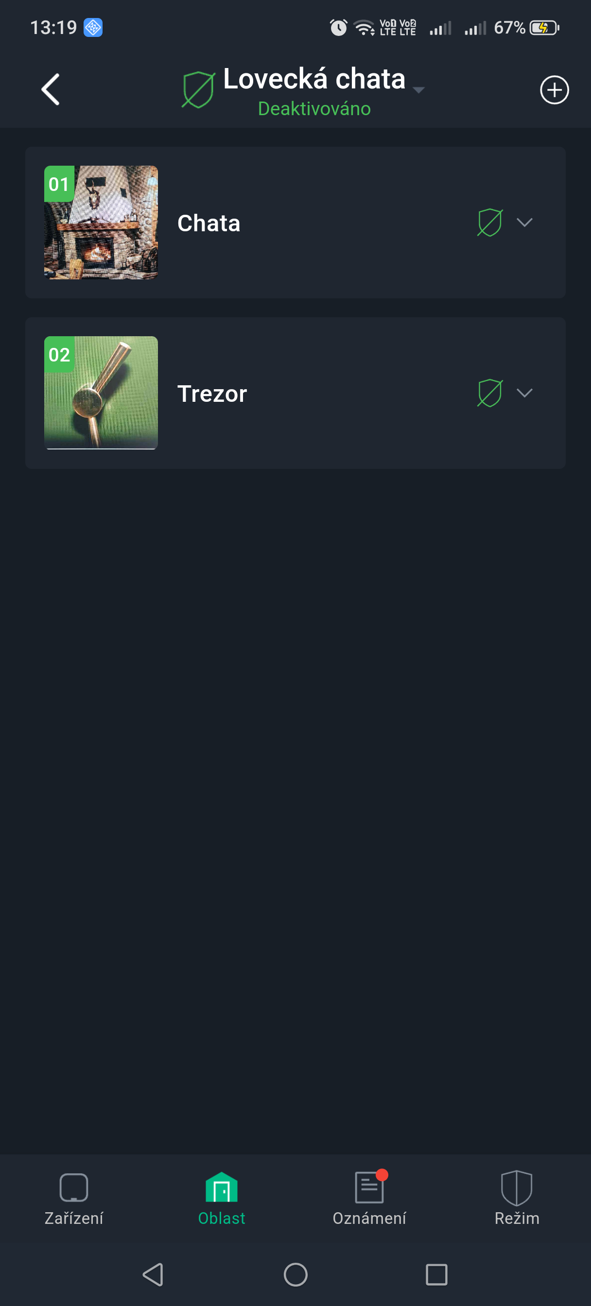
Adding an area
- On the Area screen on the Hub, tap the + icon in the top right corner to add an area.
- Configure the area, select an image for it and then tap OK.
Public Area
By setting an area as a public area, you can link it with other areas.
- If all linked areas are armed, the public area is armed automatically.
- If any of the linked areas is disarmed, the public area is disarmed automatically.
- On the Area screen on the Hub, select an area to go to its details screen.
- Tap ... in the top right corner and then tap Public Area.
- Enable the Public Area function and then tap Save.
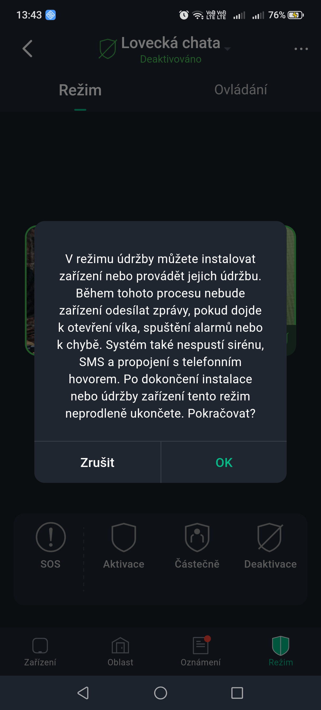
Maintenance Mode
Maintenance Mode is intended for servicing and updating devices. In Maintenance Mode, the system suspends all alarm and fault reporting for the areas, to prevent unnecessary notifications during servicing work.
- On the Control screen, tap ... in the top right corner and then tap Maintenance Mode.
Arming and disarming the system
A level 2 or 3 user has permission to arm and disarm the system. This chapter uses control via the ProSAFE app as an example.
- Before making the settings, make sure that the Hub has been added.
- Make sure that the Hub has a stable internet connection.
- Make sure that the Hub is in the Disarmed state.
You can manage the Hub and devices and perform operations such as arming and disarming or configuring alarm devices.
- On the Hub screen, tap Devices to add a device. For details on adding devices, see the user manual of the relevant device.
- Arm and disarm detectors in one area or in all areas using manual or scheduled operations:
- Individual arming and disarming: arming and disarming of detectors in one area.
- Global arming and disarming: arming and disarming of detectors in all areas.
- Manual arming and disarming: arming the security system using the ProSAFE app, keypad or controller.
- Scheduled arming and disarming: arming and disarming of detectors according to a schedule.
Individual
Detectors can be armed and disarmed in one area.
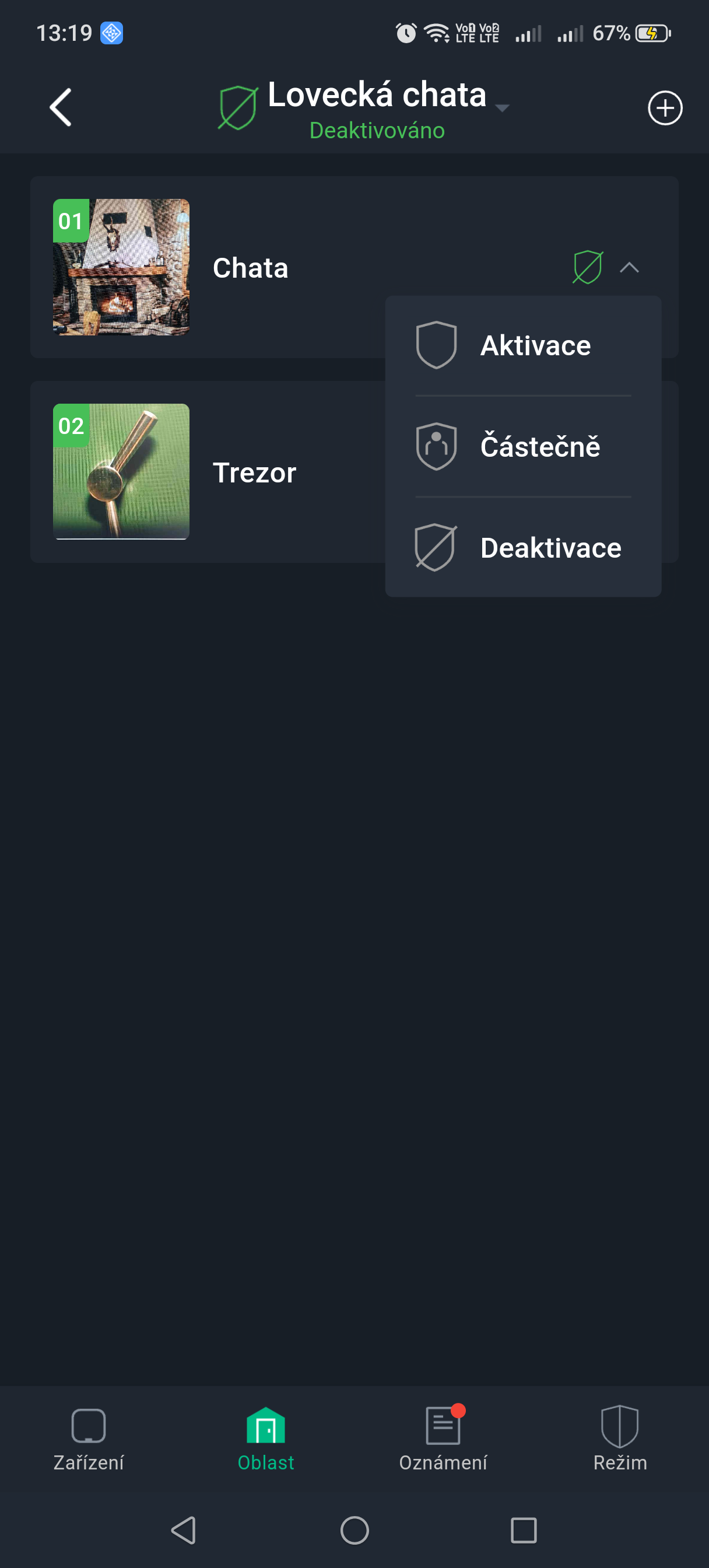
- On the Hub screen, tap Area.
- Tap the icon next to the relevant area and select one of Home Armed, Arm, Disarm:
- Home Armed: arms the system when you are inside the area of the alarm system.
- Arm (Away): arms the system when you leave the area of the alarm system.
- Disarm: switches off the security system. The opposite of arming.
Global
Detectors can be armed and disarmed in all areas.
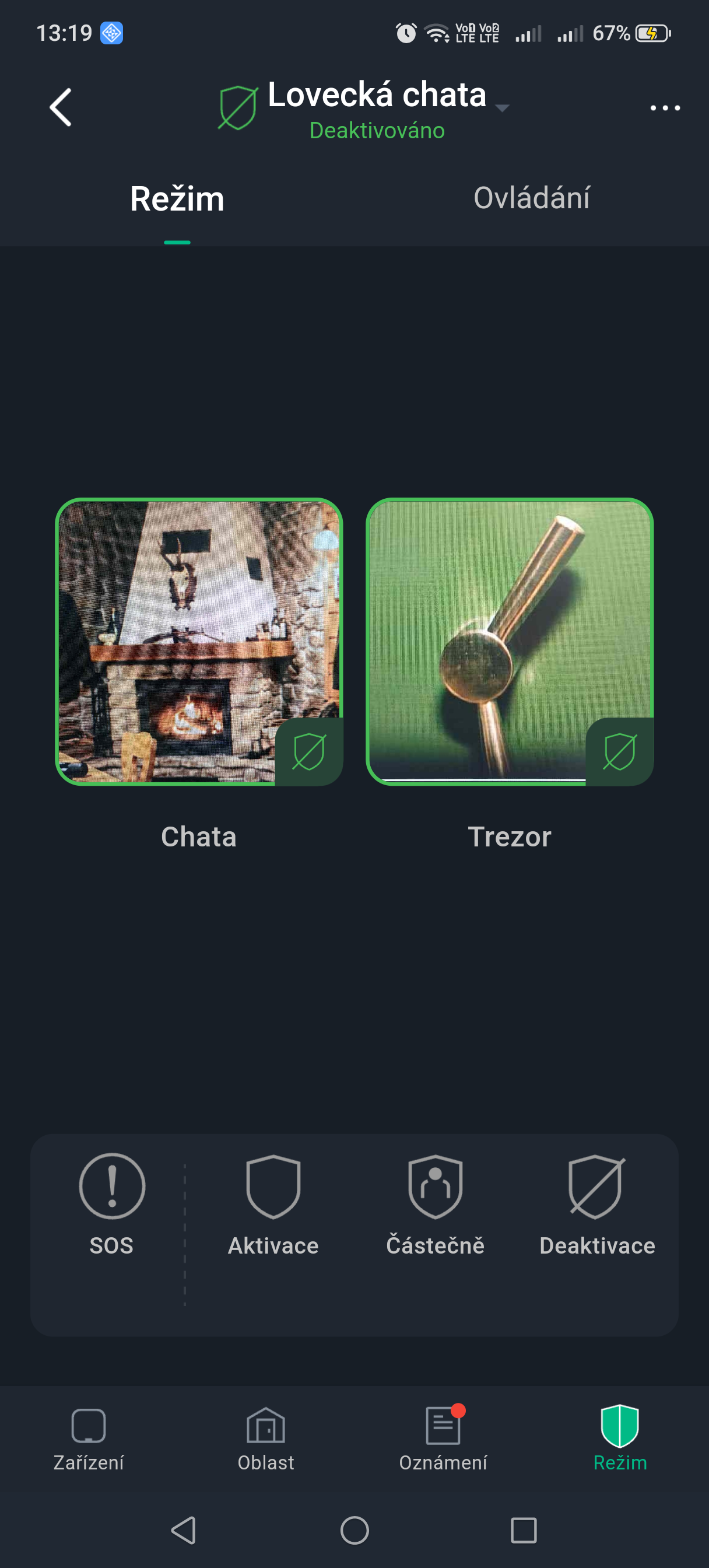
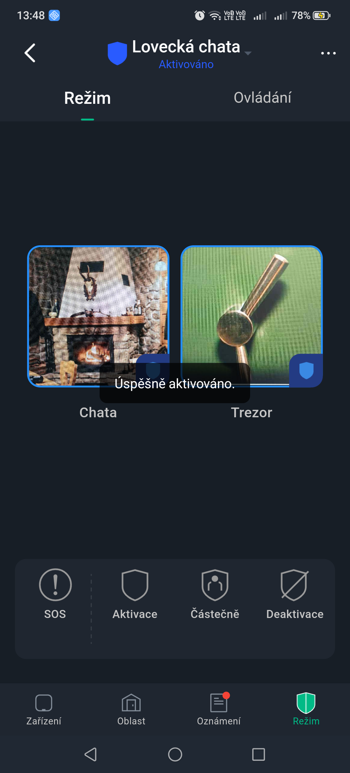
- On the Operation screen on the Hub, select one of Home Armed, Arm to arm detectors globally.
- Tap Disarm to disarm detectors globally.
- Tap SOS to trigger an alarm.
Manual (keypad, controller, card)
The security system can be armed using the ProSAFE app or a controller (keyfob).
- For the procedure for arming and disarming detectors in one area or in all areas, see the chapters Individual and Global arming and disarming.
- For control using a controller (keyfob) and keypad, you must first assign permission to control areas to the given controller and keypad. For details, see the user manual of the relevant controller and keypad.
Scheduled
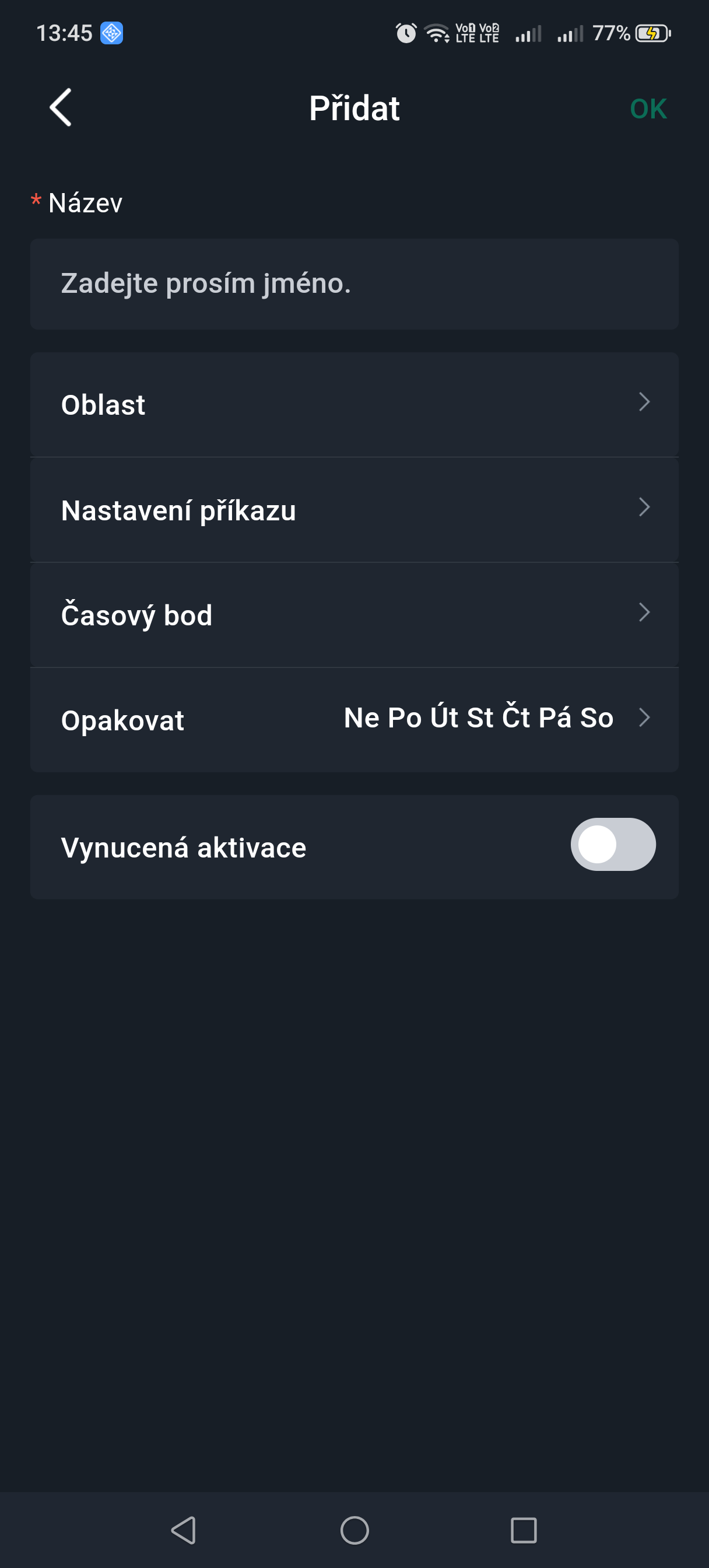
You can set a schedule for arming and disarming detectors. Arming schedules can be configured, including the arming area, modes and time periods.
- On the Hub screen, select Device Details > Settings > Hub Setting.
- Select the Scheduled arming/disarming screen, tap Add and then configure the arming schedule:
- Name: custom name of the arming schedule.
- Area: select one or more areas that you want to arm.
- Command Setting: select from Home Armed, Arm and Disarm.
- Time: set the arming time.
To apply the given arming time to other days as well, tap Repeat and select the required days.- Forced Arming: select as required.
- Click OK.
Choosing the installation location
Place the Hub inside the protected premises, ideally in the centre of them relative to the layout of the wireless devices, hidden from direct view (for example in a utility room) and within reach of a socket and the router.
Where not to install the Hub
- Outdoors.
- Near large metal objects – they shield the radio signal.
- In places with a weak mobile network signal.
- Less than 1 m from a router or power cables – sources of radio interference.
- In places where the temperature or humidity is outside the permitted range.
Installing the Hub
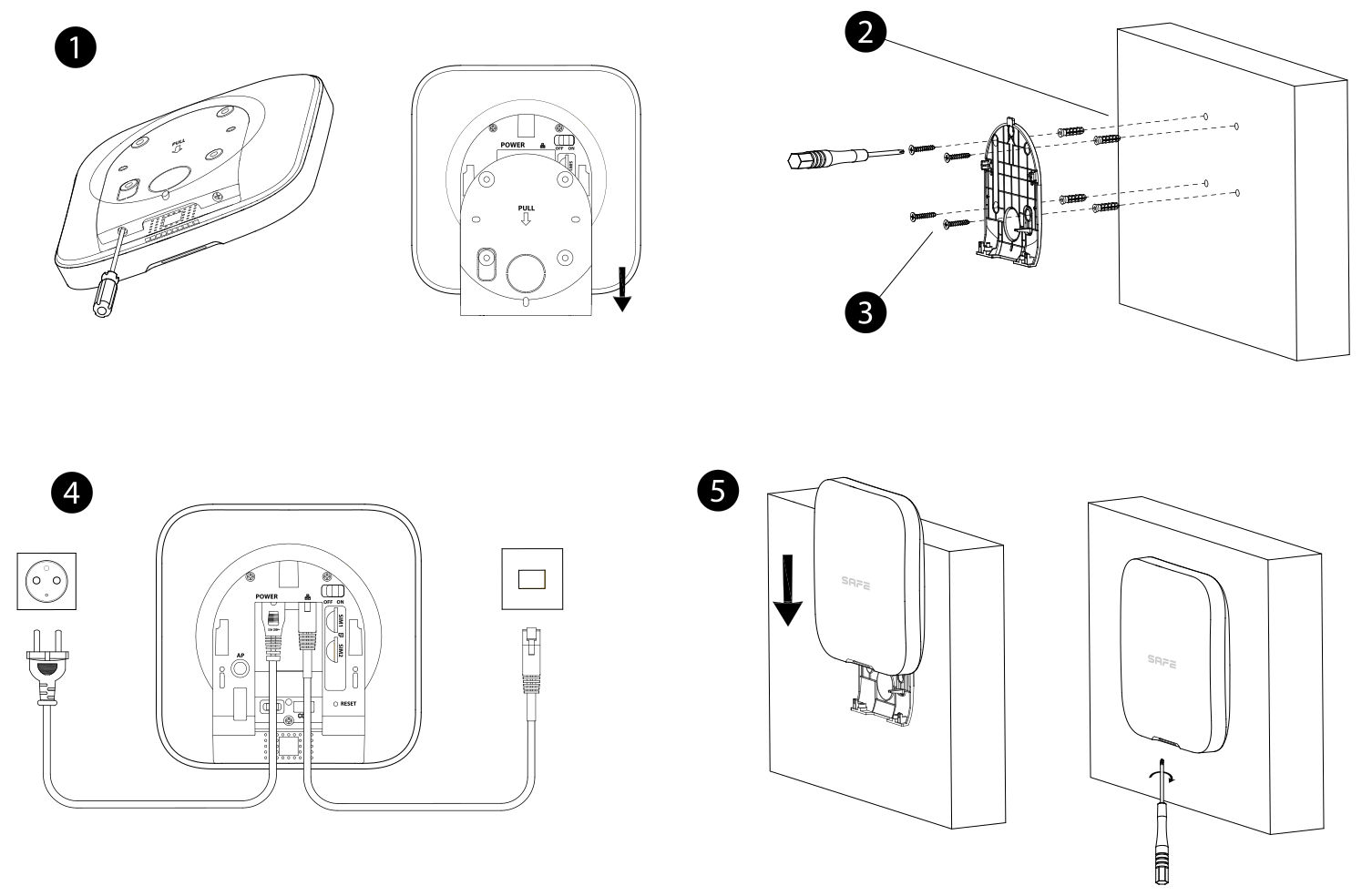
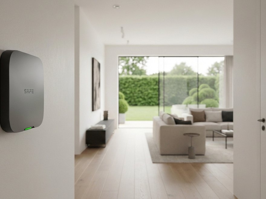
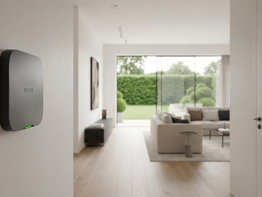
The Hub can be mounted on a wall or simply placed on a desk or shelf. Before mounting, we recommend binding the Hub to the app and checking the signal strength of all devices at the installation location.
- Remove the mounting plate from the back of the Hub (undo the bottom screws and slide the plate in the direction of the arrow).
- Drill holes according to the mounting plate and insert the wall plugs.
- Fasten the plate to the wall with ST4×25 screws.
- Connect the cables (9–15 V DC power supply, Ethernet) and place the Hub on the plate from top to bottom.
- Secure the Hub to the plate with M3×8 screws.
Power supply and backup battery
Unlike the mains-powered version, this Hub is powered by low voltage of 9–15 V DC. It therefore does not need a 230 V socket and can be operated wherever a DC supply is available – from an external battery, a solar panel with a charge controller, the on-board electrical system of a vehicle, boat or caravan, or an ordinary mains adapter.
- Input voltage 9–15 V DC; consumption from the power source max. 12 W (including charging of the backup battery).
- The built-in backup 3.7 V / 4,750 mAh lithium battery keeps the Hub in standby operation for up to 12 hours after a power failure (battery draw approx. 381 mA; during an alarm and transmission over LTE briefly up to 1,665 mA).
- The battery charges automatically at a temperature of 0 °C to +45 °C; operation without charging −10 °C to +55 °C.
- You can see the battery level as a percentage in the Hub overview; a low battery is reported by the ProSAFE app and by the DPPC.
- The battery is not user-replaceable – in the event of a fault, contact service.
Battery or solar power
When operating from an accumulator or a solar system, size the power source for the Hub's consumption of max. 12 W (including charging of the backup battery). Place a charge controller between the accumulator and the Hub to keep the voltage within the permitted range even when fully charged.
Modules IO Expander Board a IO Relay Board are powered separately 12 V DC – the Hub does not power them. If you power them from the same source as the Hub, add their power consumption (1.2 W / 1.8 W per module) to the Hub's consumption.
Protecting mobile properties
Low-voltage power allows the Hub to be deployed where a conventional electrical connection is missing or unstable – on ships, yachts, caravans, mobile homes, containers, and lorries and transport vehicles. In such a case, pay attention to two things:
- Power quality – the voltage in on-board electrical systems fluctuates; make sure it stays within the 9–15 V DC range even when the engine is started or appliances are switched on.
- Mobile network availability – for properties that move, expect temporary outages. The Hub has two SIM card slots; insert cards from two different operators so that it switches to the other network if the signal is lost.
Maintenance
- Regularly update the firmware of the Hub and of the devices (cloud update) and the ProSAFE app.
- Check the system status: network connection, battery level, tamper and the connection to the DPPC.
- Regularly review the event log and the list of logged-in users.
- Test the functionality of the devices using Test Mode and the connection to the DPPC using the communication test.
- Clean the cover with a dry, soft cloth, without solvents or aggressive cleaning agents.
Technical specifications
| MODELOVÉ OZNAČENÍ | |
| SAFE 38300 | White version, EAN 0728204235157 |
| SAFE 38301 | Black version, EAN 0728204235140 |
| PORT | |
| Alarm input | Expandable, 64 channels |
| Alarm output | Expandable, 64 channels |
| BEZDRÁTOVÁ ZAŘÍZENÍ | |
| Device | 150 devices (wireless and wired), specifically: up to 64 wireless remote controls (keyfobs); up to 8 wireless keypads; up to 6 wireless sirens (including 4 communicating/intercom sirens); up to 6 wireless signal repeaters; up to 64 wireless PIR-Cam detectors (indoor PIR cameras, outdoor PIR cameras and dual/triple detectors); up to 16 multifunction I/O transmitters; up to 16 RS-485 expanders (input and output expanders) |
| DRÁTOVÁ ZAŘÍZENÍ | |
| Wired elements | 64 wired zones (third-party components can be integrated) |
| OBLASTI | |
| Number of areas (rooms) | 32 |
| SÍŤ | |
| Network mode | Ethernet, Wi-Fi and mobile network (supports installation of two SIM cards, only one of which can be active at a time) |
| Network port | 1× RJ-45, 10 Mbps/100 Mbps Ethernet port |
| RS-232 port | 1× RS-232 port for Serial Bridge SAFE 38181 |
| Backup battery | 1× built-in rechargeable lithium battery, 4,750 mAh |
| VIDEO A AUDIO | |
| Video input | Up to 8 integrated IP cameras |
| Audio output | 1 channel |
| Volume control | Yes |
| Voice announcements | By telephone and via the local speaker |
| FUNKCE | |
| Indicator (LED) | Indicates alarm status, arming and disarming, network connection and device fault |
| Buttons | Reset button, power button and AP switch |
| SMS | Yes (up to 12 telephone numbers) |
| Phone call | Yes (up to 12 telephone numbers) |
| Video linkage | Yes |
| Offline cache | Stores up to 50 alarm messages |
| Arming and disarming method | App, keypad, remote control (keyfob), RFID card, scene, ext. device input |
| Remote update | Cloud update |
| Low battery detection | Yes |
| Tamper contact | Yes |
| User management | 33 app users (1 owner, 31 other users and 1 installer) and 32 keypad users |
| Event log | Up to 5,000 entries |
| Transmission protocol | SIA, SoftGuard |
| BEZDRÁTOVÁ KOMUNIKACE | |
| Frequency band | 868.0–868.6 MHz |
| Transmit power (EIRP) | Max. 25 mW |
| Communication mechanism | Two-way communication |
| Communication range | Up to 2,000 m (6,561.68 ft) in open space |
| Encryption | AES128 |
| Frequency hopping | Yes |
| VŠEOBECNÉ | |
| Language support | 18 languages: Arabic, Czech, Danish, Dutch, English, French, German, Italian, Portuguese (Europe), Russian, Spanish (Latin America), Spanish (Europe), Turkish, Slovak, Polish, Greek, Bulgarian, Estonian. English is set as the default. |
| Power supply | Input voltage 9–15 V DC |
| Backup time (standby) | A fully charged battery lasts up to 12 hours under the following conditions: the Hub is connected to Wi-Fi, is linked to the DPPC, the heartbeat interval is 1,800 s, and 8 devices and the cloud are connected. |
| Power consumption | From the power source max. 12 W (including battery charging); on battery operation 381 mA (standby) to 1,665 mA (maximum) |
| Operating temperature | Without battery charging: −10 °C to +55 °C (+14 °F to +131 °F); while the battery is charging: 0 °C to +45 °C (+32 °F to +113 °F) |
| Operating humidity | 10–90 % RH |
| Product dimensions | 174.8 × 174.8 × 38.3 mm (6.88" × 6.88" × 1.51") (L × W × H) |
| Net weight | 510 g (1.12 lb) |
| Gross weight | 860 g (1.90 lb) |
| Installation | Supports wall mounting and free-standing placement on a desk |
| Housing material | PC + ABS |
| Storage temperature | −10 °C to +55 °C (+14 °F to +131 °F) |
| Storage humidity | 10–90 % RH |
| Package dimensions | 254 × 211 × 61 mm (10.00" × 8.31" × 2.40") (L × W × H) individually in the inner box; 524 × 508 × 442 mm (20.63" × 20.00" × 17.40") (L × W × H) in the shipping carton |
| CERTIFIKACE | |
| Certification | EN 50131-1:2006+A1:2009+A2:2017+A3:2020; EN 50131-3:2009; EN 50131-6:2017+A1:2021; EN 50131-5-3:2017; EN 50131-10:2014; EN 50136-2:2013+A1:2023; CE. Security Grade 2, Environmental Class II, ATS SP2/DP2. |
| Compatibility | ProSAFE app 1.99.700+; SAFEWatch / SAFEWatch Pro; Serial Bridge SAFE 38181; IO Expander Board SAFE 38182; IO Relay Board SAFE 38183 |
| Corrosion protection rating | Basic protection. The product is intended for normal use and is also suitable for premises with no special corrosion protection requirements. |
| ZÁRUKA | |
| Warranty period | 36 months |
| WI-FI | |
| Wi-Fi standard | IEEE 802.11b/g/n |
| Wi-Fi frequency band | 2400–2483.5 MHz |
| Wi-Fi transmit power | ≤ 20 dBm @ 2400–2483.5 MHz |
| MOBILNÍ SÍŤ | |
| Mobile network frequency band (EU) | 4G: FDD-LTE B1/B3/B7/B8/B20/B28A; TDD-LTE B38/B40/B41; 3G: WCDMA B1/B8; 2G: GSM 1 800/900 MHz |
| Transmit power (EIRP) | 4G: power class 3: 23 dBm ±2 dB; 3G: power class 3: 24 dBm +1/−3 dB; 2G: power class 0: 30 dBm ±3 dB (GSM900), power class 5: 33 dBm ±3 dB (GSM1800) |
ATE category (EN 50136-1)
| Category | Reporting time | Protocols | PSTN | 2G/3G | IP | Communication devices to be used |
|---|---|---|---|---|---|---|
| SP2 | 25 h | Standard | ✓ | One designated communication device | ||
| SP3 | 30 min | Standard | ✓ | ✓ | Only one of the two designated communication devices | |
| SP4 | 3 min | Encrypted | ✓ | ✓ | Only one of the two designated communication devices | |
| SP5 | 90 s | Encrypted | ✓ | ✓ | Only one of the two designated communication devices | |
| DP1 | 25 h | Standard | ✓ | ✓ | ✓ | Only two of the three designated communication devices |
| DP2 | 30 min | Standard | ✓ | ✓ | ✓ | Only two of the three designated communication devices |
| DP3 | 3 min | Encrypted | ✓ | ✓ | Both designated communication devices | |
| DP4 | 90 s | Encrypted | ✓ | ✓ | Both designated communication devices |
ATE: Alarm Transmission Equipment.
SPx (Single Path): a value expressing the performance level achieved by a single communication device in accordance with EN 50136-1.
DPx (Double Path): a value expressing the performance level achieved by a combination of two communication devices in accordance with EN 50136-1.
Reporting time: the maximum time available for reporting a fault of the alarm transmission equipment. The device meets this requirement by regularly reporting its status using a specific test function.
Protocols: indicate the security level of the protocols used for fault reporting. Standard and voice protocols are encrypted. Highly secure protocols are encrypted with a 128-bit or 256-bit AES key.
Communication devices: the communication devices implemented.
Communication devices to be used: indicates the number and type of communication devices to be used according to the ATE category.
SP2: LAN/Wi-Fi via the cloud, the ProSAFE app (default reporting time 150 s), or the DPPC (min. reporting time 25 h).
DP2: primarily LAN/Wi-Fi via the cloud, the ProSAFE app (default reporting time 150 s), or the DPPC (min. reporting time 30 min), and secondarily GPRS/4G via the cloud, the ProSAFE app (default reporting time 150 s), or the DPPC (min. reporting time 30 min).
Package contents
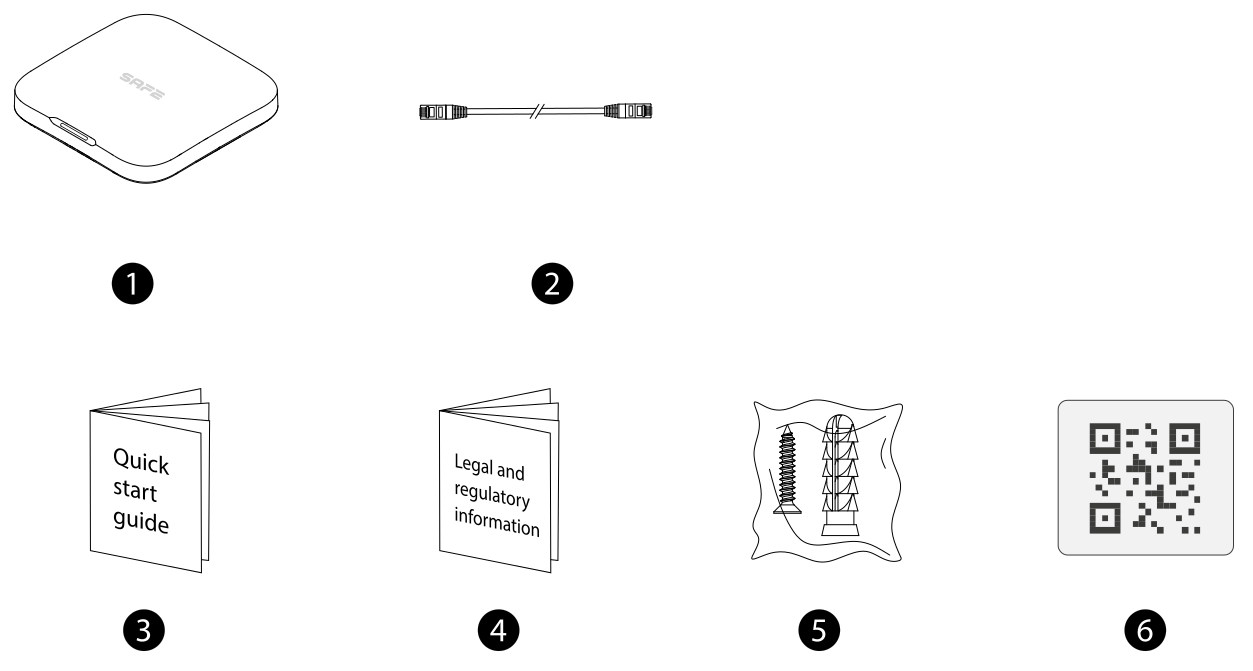
- Hub – 1 pc
- Ethernet cable – 1 pc
- Quick start guide – 1 pc
- Legal and regulatory information – 1 pc
- Set of screws and wall plugs
- QR code – 1 pc
Safety notices
This manual describes the installation, functions and operation of the alarm Hub (hereinafter the “Hub”). Read this manual carefully before using the device and keep it for future reference.
Signal words
The following signal words and symbols may appear in this manual.
- NEBEZPEČÍ – Indicates a high potential hazard which, if not avoided, will result in death or serious injury.
- VAROVÁNÍ – Indicates a medium or lower-level potential hazard which, if not avoided, may result in minor or moderate injury.
- UPOZORNĚNÍ – Indicates a potential risk which, if not avoided, may result in property damage, data loss, reduced performance or unpredictable results.
- ESD symbol – Indicates a device sensitive to electrostatic discharge (Electrostatic Sensitive Devices).
- High voltage – Indicates dangerous high voltage. Take care not to come into contact with electricity.
- Laser radiation – Indicates a laser radiation hazard. Take care not to expose yourself to the laser beam.
- Tip – Offers a procedure for solving a problem or saving time (referred to in the text as a “tip” type note).
- Note – Provides additional information to supplement the text.
In this document, tips and additional information are shown as boxes with a note (div class="note"), whereas safety-critical instructions are shown as boxes with a warning (div class="warn").
Personal data protection
As a user of the device or a data controller, you may collect the personal data of third parties, such as their likeness, voice recording, fingerprints or vehicle registration plate. It is your duty to comply with local data protection laws in order to protect the legitimate interests of the persons concerned. These measures include, but are not limited to: placing a clear and visible notice informing people of the existence of a monitored area and providing the necessary contact details.
About this manual
This manual serves as an informational document only – minor differences may occur between the manual and the actual product, the manual may change in line with current legislation and technical modifications of the product, and all trademarks and company names mentioned in the manual are the property of their respective owners. In case of doubt or dispute, or if problems occur while using the device, contact the supplier or customer service; the manufacturer reserves the right of final interpretation of the contents of the manual.
Operating requirements
The device or remote control contains button cell batteries. Do not swallow the batteries – there is a risk of chemical burns.
Possible consequence: A swallowed button cell battery can cause severe internal burns and death within 2 hours.
Precautions (among others):
- Keep new and used batteries out of the reach of children.
- If the battery compartment does not close securely, stop using the product immediately and keep it out of the reach of children.
- If you suspect that a battery has been swallowed or inserted into any part of the body, seek medical attention immediately.
- Before use, make sure the device's power supply is working properly.
- Do not unplug the device's power cable while it is switched on.
- Use the device only within its rated power range.
- Transport, use and store the device only within the permitted humidity and temperature.
- Prevent liquids from splashing or dripping onto the device. Make sure that no objects filled with liquid are placed on the device, so that liquid cannot get inside it.
- Do not disassemble the device.
Installation requirements
- Before switching on the device, first connect it to a 9–15 V DC direct-current power source.
- Strictly observe local electrical safety standards and make sure that the voltage in the area is stable and meets the power supply requirements of the device.
- Do not connect the device to more than one power source. Otherwise the device may be damaged.
- When powering the device, observe the following electrical requirements:
- Requirements for selecting a power adapter:
- The power supply must meet the requirements of IEC 60950-1 and IEC 62368-1.
- The voltage must meet the SELV (Safety Extra Low Voltage) requirements and must not exceed the ES-1 standard.
- If the device's power does not exceed 100 W, the power supply must meet the LPS requirements and must not exceed the PS2 level.
- When selecting a power supply, follow the power requirements stated on the device label – the output voltage must be within the range 9–15 V DC and the power supply must cover the consumption of the Hub (max. 12 W) and of the IO modules, if it also powers them.
- Requirements for selecting a power adapter:
- When working at height, observe all safety procedures and use the prescribed protective equipment.
- Do not expose the device to direct sunlight or sources of heat.
- Do not install the device in damp, dusty or smoky areas.
- Install the device in a well-ventilated place and do not cover its ventilation openings.
- Connect Class I electrical appliances to a socket with a protective earth.
Appendix 1 — Events preventing arming
Device
| Event | Description |
|---|---|
| ModuleLoss (device offline) | The device was offline. |
| HeartError (heartbeat missing) | No heartbeat packets were sent for more than 18 minutes. |
| Alarm (24-hour zone) | Alarm (24-hour zone). |
| Open (rear cover opened) | The rear cover of the device was opened. |
| exOpen (external device cover opened) | The rear cover of the external device was opened. |
| Tamper | The device's tamper alarm was triggered. |
| LowBattery (low battery) | A low battery was detected in the device. |
| PriPowerLoss (main power failure) | A main power fault was detected in the device. |
| BatteryLoss (battery fault) | A battery fault was detected. |
| OverVoltage (overvoltage) | Overvoltage was detected. |
| OverCurrent (overcurrent) | Overcurrent was detected. |
| OverHeat (overheating) | Overheating was detected. |
| FireAlarm (fire alarm) | A fire alarm was triggered. |
| MedicalAlarm (medical alarm) | A medical alarm was triggered. |
| SOS Alarm | An SOS alarm was triggered. |
| PanicAlarm (panic alarm) | A panic alarm was triggered. |
| Gas Alarm (gas leak alarm) | A gas leak alarm was triggered. |
| IntrusionAlarm (intrusion alarm) | An intrusion alarm was triggered. |
| HoldUpAlarm (hold-up alarm) | A hold-up alarm was triggered. |
Hub
| Event | Description |
|---|---|
| SOSAlert (SOS alert) | A panic alarm can be triggered via the ProSAFE app. |
| Tamper | The Hub's tamper alarm was triggered. |
| Server Connect Error (server connection error) | The Hub was offline. |
| SIAServer Connect Error (SIA server connection error) | A connection error occurred between the Hub and the DPPC (SIA). |
| LowBattery (low battery) | A low battery was detected. |
| MainLoss (main power failure) | A main power fault was detected. |
| BatteryLoss (battery fault) | A battery fault was detected. |
| NoGSM (GSM module error) | A 2G/4G module error was detected. |
| ATS Fault (transmission system fault) | An alarm transmission system (ATS) fault was detected. |
| Cellular Network ATP Fault (transmission path fault – mobile network) | An alarm transmission path fault was detected (mobile network outage). |
| Wired Network/Wi-Fi ATP Fault (transmission path fault – Ethernet/Wi-Fi) | An alarm transmission path fault was detected (Ethernet or Wi-Fi outage). |
| AP Mode (access point mode) | An access point (AP) mode fault was detected. |
Appendix 2 – SIA event codes
| Č. | Event | Code / SIA code | Description |
|---|---|---|---|
| 1 | Medical Alarm | 1100 / MA | The medical alarm button was pressed |
| 2 | Medical alarm ended | 3100 / MH | The medical alarm button was restored |
| 3 | Fire Alarm | 1110 / FA | Fire alarm |
| 4 | Fire alarm ended | 3110 / FH | Fire alarm ended |
| 5 | Duress Alarm | 1121 / HA | Duress alarm |
| 6 | Silent Panic Alarm | 1122 / HA | The panic alarm button / hold-up button was pressed |
| 7 | Silent panic alarm ended | 3122 / HH | The panic alarm button / hold-up button was restored |
| 8 | Audible Panic Alarm | 1123 / PA | The panic alarm button / hold-up button was pressed |
| 9 | Audible panic alarm ended | 3123 / PH | The panic alarm button / hold-up button was restored |
| 10 | Burglary Alarm | 1130 / BA | Motion detected; opening detected; external contact open; intrusion alarm; glass break detected; tilt detected; shock detected |
| 11 | Intrusion alarm ended | 3130 / BR | Motion ended; closing detected; external contact closed; intrusion alarm ended; glass break ended; tilt ended; shock ended |
| 12 | Perimeter Alarm | 1131 / BA | Tripwire alarm |
| 13 | Perimeter alarm ended | 3131 / BR | Tripwire alarm ended |
| 14 | 24 Hour Alarm | 1133 / BA | Motion detected; opening detected; external contact open; glass break detected; tilt detected; shock detected |
| 15 | 24-hour alarm ended | 3133 / BR | Motion ended; closing detected; external contact closed; intrusion alarm ended; glass break ended; tilt ended; shock ended |
| 16 | Entry Or Exit Alarm | 1134 / BA | Motion detected; opening detected; external contact open; glass break detected; tilt detected; shock detected |
| 17 | Entry/exit zone alarm ended | 3134 / BR | Motion ended; closing detected; external contact closed; intrusion alarm ended; glass break ended; tilt ended; shock ended |
| 18 | Lid Was Opened | 1137 / TA | Lid opened; external lid opened; device was moved |
| 19 | Lid Was Closed | 3137 / TR | Lid closed; external lid closed; device is no longer being moved |
| 20 | Expansion Module Was Disconnected | 1143 / EM | The camera module was disconnected |
| 21 | Expansion Module Was Connected | 3143 / EN | The camera module is connected |
| 22 | Masking Alarm | 1149 / TA | Masking alarm |
| 23 | Masking alarm ended | 3149 / TR | Masking alarm ended |
| 24 | Gas Leakage | 1151 / GA | Gas leak detected |
| 25 | Gas leak ended | 3151 / GH | Gas leak ended |
| 26 | Water Leakage | 1154 / WA | Water leak detected |
| 27 | Water leak ended | 3154 / WH | Water leak ended |
| 28 | High Temperature | 1158 / KA | High temperature |
| 29 | Normal Temperature | 3158 / KH | Normal temperature |
| 30 | Low Temperature | 1159 / ZA | Low temperature |
| 31 | Normal Temperature | 3159 / ZH | Normal temperature |
| 32 | Main Power Failure | 1301 / AT | Main power failure |
| 33 | Main Power Restored | 3301 / AR | Main power restored |
| 34 | Low Battery | 1302 / YT | Low battery |
| 35 | Battery Level Restored | 3302 / YR | Battery level restored |
| 36 | Battery Fault | 1311 / YM | Battery fault |
| 37 | Battery Restored | 3311 / YR | Battery restored |
| 38 | Overcurrent Protection Triggered | 1312 / YI | Overcurrent protection triggered |
| 39 | Overcurrent Protection Restored | 3312 / YJ | Overcurrent protection restored |
| 40 | Overheat Protection Triggered | 1318 / KA | Overheat protection triggered |
| 41 | Overheat Protection Restored | 3318 / KH | Overheat protection restored |
| 42 | Overvoltage Protection Triggered | 1319 / YP | Overvoltage protection triggered |
| 43 | Overvoltage Protection Restored | 3319 / YQ | Overvoltage protection restored |
| 44 | RF Jamming | 1344 / XQ | RF jamming |
| 45 | ATS Fault | 1350 / NT | ATS fault; Ethernet fault; Wi-Fi fault; mobile network fault |
| 46 | ATS Restored | 3350 / NR | ATS restored; Ethernet restored; Wi-Fi restored; mobile network restored |
| 47 | Communication Failure | 1354 / YS | RF-HD connection failed |
| 48 | Communication Restored | 3354 / YK | RF-HD connection restored |
| 49 | Wireless Device Was Disconnected | 1355 / XL | Connection lost |
| 50 | Wireless Device Was Connected | 3355 / XC | Connection restored |
| 51 | Protection Loop Shorted | 1372 / QT | Protection loop shorted |
| 52 | Fixed The Shorted Protection Loop | 3372 / QR | Shorted protection loop fixed |
| 53 | Sensor Fault | 1380 / AS | Sensor fault |
| 54 | Sensor Restored | 3380 / AN | Sensor fault cleared |
| 55 | Disarmed By APP | 1400 / OQ | Disarmed |
| 56 | Armed by app (Armed By APP) | 3400 / CQ | Armed |
| 57 | Disarmed by keypad (Disarmed By Keypad) | 1401 / OP | Disarmed |
| 58 | Armed by keypad (Armed By Keypad) | 3401 / CL | Armed |
| 59 | Disarmed by schedule (Disarmed By Schedule) | 1403 / OA | Disarmed |
| 60 | Armed by schedule (Armed By Schedule) | 3403 / CA | Armed |
| 61 | Cancel (Cancel) | 1406 / BC | Cancel |
| 62 | Disarmed by keyfob (Disarmed By Keyfob) | 1407 / OS | Disarmed |
| 63 | Armed by keyfob (Armed By Keyfob) | 3407 / CS | Armed |
| 64 | Quick arming (Quickly Armed) | 3408 / CS | Armed |
| 65 | Disarmed by key switch (Disarmed By KeySwitch) | 1409 / OS | Disarmed |
| 66 | Armed by key switch (Armed By KeySwitch) | 3409 / CS | Armed |
| 67 | Home Armed mode activated (Home Mode Activated) | 3441 / NL | Home Armed mode activated |
| 68 | Home Armed mode activated by key switch (Home Mode Activated By KeySwitch) | 3442 / NL | Home Armed mode activated |
| 69 | Armed with faults (Armed With Faults) | 3450 / CF | Armed with faults |
| 70 | Unsuccessful arming (Unsuccessful Arming) | 1454 / CI | Unsuccessful arming |
| 71 | Unsuccessful arming by schedule (Unsuccessful Arming By Schedule) | 1455 / CD | Unsuccessful arming |
| 72 | Exit error (Exit Error) | 1457 / EA | Unsuccessful arming |
| 73 | Device locked (Device Locked) | 1501 / DK | Device locked |
| 74 | Device unlocked (Device Unlocked) | 3501 / DO | Device unlocked |
| 75 | Device deactivated (Deactivated Device) | 1502 / QB | Permanently deactivated |
| 76 | Device reactivated (Reactivated Device) | 3502 / QU | Device has been reactivated |
| 77 | Tamper disabled (Disabled Tamper) | 1503 / TB | Cover permanently deactivated |
| 78 | Tamper enabled (Enabled Tamper) | 3503 / TU | Cover enabled |
| 79 | Device bypassed (Bypassed Device) | 1570 / QB | Bypassed |
| 80 | Device bypass cancelled (Device Bypass Restored) | 3570 / QU | Restored |
| 81 | Tamper bypassed (Bypassed Tamper) | 1578 / TB | Tamper signal bypassed |
| 82 | Tamper bypass cancelled (Tamper Bypass Restored) | 3578 / TU | Tamper signal restored |
| 83 | Manual test report (Manual Trigger Test Report) | 1601 / RX | Test report |
| 84 | Periodic test report (Periodic Test Report) | 1602 / RP | Periodic test report |
| — | Heartbeat | Null / Null | Heartbeat reported by the device |
Appendix 3 — Cybersecurity
SAFE HOME attaches great importance to cybersecurity and privacy protection, and continuously invests in raising the security awareness and capabilities of its employees and in ensuring an appropriate level of product security. SAFE HOME has established a dedicated security team that ensures security throughout the entire product life cycle – from design, development and testing to production, delivery and maintenance. The company follows the principles of data collection minimisation, service minimisation, a ban on implementing hidden access (backdoors), and the removal of unnecessary and insecure services (e.g. Telnet). SAFE HOME products continue to introduce innovative security technologies and strive to raise the level of product security, providing users worldwide with security advisories and round-the-clock (24/7) response to security incidents in order to better protect their rights and interests. SAFE HOME also invites users, partners, suppliers, government authorities, industry organisations and independent researchers to report any potential risks or vulnerabilities found on SAFE HOME devices to the SAFE HOME PSIRT security team; for the specific reporting procedure, see the cybersecurity section on the manufacturer's website.
Product security requires not only the continuous attention and effort of the manufacturer in development, production and supply, but also the active participation of users, who can contribute to improving the environment and manner in which the product is used, and thus better ensure its security once it has been put into service. For this reason, we recommend that users operate the device securely, including by taking the following measures:
Account management
- Use strong passwords. When choosing a password, follow these recommendations:
- at least 8 characters long;
- contains at least two types of characters: upper- and lower-case letters, digits and symbols;
- does not contain the account name or the account name in reverse order;
- does not contain consecutive characters, for example 123, abc, etc.;
- does not contain repeated characters, for example 111, aaa, etc.
- Change passwords regularly. It is recommended to change the device password regularly to reduce the risk of it being guessed or cracked.
- Assign accounts and permissions appropriately. Add users according to actual operational and administrative needs and grant them the minimum permissions necessary.
- Keep the account lockout function enabled. The account lockout function is enabled by default. We recommend keeping it active to protect the account – after repeated unsuccessful password attempts, the account concerned and the source IP address are locked.
- Set up and promptly update password recovery information. SAFE HOME devices support a password recovery function. To reduce the risk of an attacker abusing this function, update this information whenever anything changes. When setting security questions, it is recommended not to use easily guessable answers.
Service configuration
- Enable HTTPS. We recommend enabling HTTPS to access web services through a secure channel.
- Encrypted audio and video transmission. If the content of your audio/video data is important or sensitive, we recommend using the encrypted transmission function to reduce the risk of it being intercepted during transmission.
- Disable unnecessary services and use secure mode. If they are not needed, we recommend disabling certain services, such as SSH, SNMP, SMTP, UPnP, access point (AP) and the like, to reduce the potential attack surface. Where necessary, we strongly recommend choosing secure modes, including for the following services:
- SNMP: choose SNMP v3 and set strong encryption and authentication passwords;
- SMTP: choose TLS for access to the mail server;
- FTP: choose SFTP and set complex passwords;
- access point (AP): choose the WPA2-PSK encryption mode and set complex passwords.
- Change the default HTTP and other service ports. We recommend changing the default HTTP and other service ports to any port in the range 1024–65535 to reduce the risk of an attacker guessing them.
Network configuration
- Enable the allowlist. We recommend enabling the allowlist function and allowing access to the device only from IP addresses on this list. Remember, therefore, to add the IP address of your computer and associated devices to the list.
- MAC address binding. We recommend binding the gateway IP address to its MAC address on the device to reduce the risk of ARP spoofing.
- Build a secure network environment. To better ensure device security and reduce potential cyber risks, it is recommended to:
- disable the port mapping function on the router so that devices on the internal network cannot be accessed directly from the external network;
- segment the network according to actual needs: if no communication is required between two subnets, it is recommended to use VLANs, a gateway and other methods to separate the networks and achieve their isolation;
- deploy an 802.1x access authentication system to reduce the risk of unauthorised access by end devices to the private network.
Security audit
- Check logged-in users. It is recommended to check logged-in users regularly in order to detect unauthorised users.
- Check the device log. By viewing the logs, you can find out the IP addresses from which someone is attempting to log in to the device, as well as the key operations of logged-in users.
- Set up the network log. Because the device's storage capacity is limited, the stored log is limited. If you need to keep the log for a long time, we recommend enabling the network log function so that key records are synchronised to a log server for later retrieval.
Software security
- Update firmware promptly. In line with common operating standards, the device firmware should be updated promptly to the latest version so that the device has the latest features and security. If the device is connected to a public network, we recommend enabling automatic detection of online updates so that firmware update information from the manufacturer is obtained in good time.
- Update client software promptly. We recommend downloading and using the latest version of the client software (the ProSAFE app).
Physical protection
We recommend ensuring physical protection of the device (especially storage devices) – for example by placing the device in a dedicated room and cabinet and introducing access control and key management – to prevent unauthorised persons from damaging the hardware and other peripheral devices (e.g. USB flash drive, serial port).
Warranty
A warranty is provided on the SAFE Hub 2 Plus LTE device 36 months from the date of sale. The warranty does not cover defects caused by failure to follow the instructions given in this manual.
In case of problems with the device, first contact technical support – most situations can be resolved remotely.
Gallery
Need help?
SAFE HOME europe technical support:
E-mail: info@safe-home.eu · Telephone: (+420) 581 222 262
Web: www.smart-safe.eu