
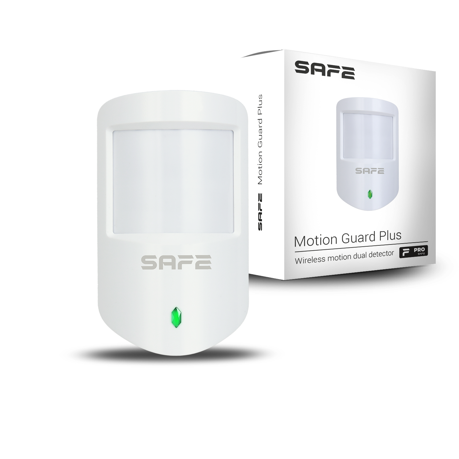
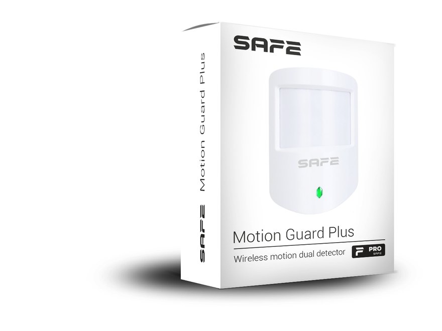
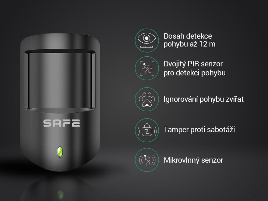
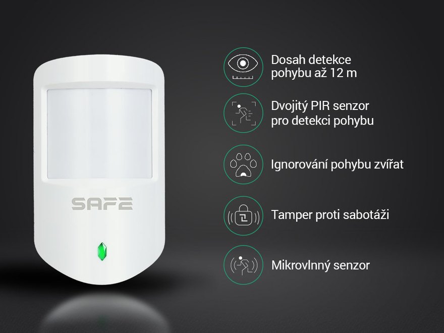
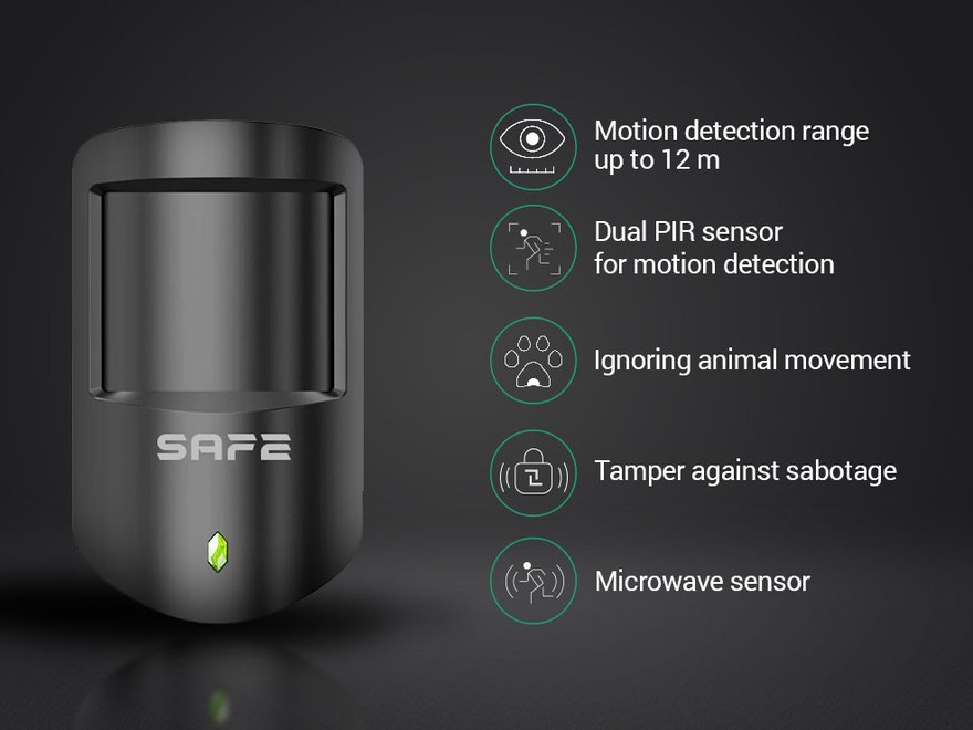
Motion Guard Plus is a wireless dual PIR motion detector with a microwave sensor that detects motion at a distance of up to 12 meters and reliably ignores the movement of animals in the protected area (PET immunity) up to a weight of 18 kg and a height of 50 cm, drafts, and other potential causes of false alarms. It communicates with the SAFE system using an encrypted protocol SAFE Keeper at a distance of up to 1 600 m in open space.
Preface
General
This user manual introduces the installation, functions, and operation of the wireless dual motion detector (hereinafter referred to as the "detector"). Before using the device, please read this manual carefully and keep it for future reference.
Safety Instructions
The following signal words may appear in the user manual:
| Signal Word | Meaning |
|---|---|
| DANGER | Indicates a high potential hazard that, if not avoided, may result in death or serious injury. |
| WARNING | Indicates a medium or low potential hazard that could cause minor or moderate injury if not avoided. |
| CAUTION | Indicates a potential risk that could lead to property damage, data loss, reduced performance, or an unpredictable outcome. |
| TIP | Provides methods to help you solve a problem or save time. |
| NOTE | Provides additional information, such as emphasis and supplementary text. |
Revision History
| Version | Revision Content | Release Date |
|---|---|---|
| V1.0.0 | First release. | August 2026 |
Privacy Notice
As a device user or data controller, you may collect personal data of others, such as their face, fingerprints, and license plate number. You must comply with local privacy laws and regulations to protect the legitimate rights and interests of other people by implementing measures that include, among others: providing clear and visible identification to inform people of the existence of the monitored area and providing the required contact information.
About the Manual
- The user manual serves as a reference guide only. There may be minor differences between the information provided and the product.
- We are not liable for any damage resulting from using the product in a manner that does not comply with the instructions in the user manual.
- The manual will be updated according to the latest laws and regulations of the relevant jurisdictions. For detailed information, refer to the printed user manual, scan the QR code, or visit our official website. The manual is for reference purposes only. There may be minor differences between the electronic and paper versions.
- All designs and software are subject to change without prior written notice. Due to product updates, certain differences may occur between the product and the information in the manual. Customer service will provide you with the latest version of the software and supplementary documentation.
- There may be printing errors or discrepancies in the description of functions, operations, and technical data. In the event of doubt or dispute, we reserve the right of final explanation. If the manual (in PDF format) cannot be opened, update your reader software or try a different common reader software.
- All trademarks, registered trademarks, and company names in the manual are the property of their respective owners.
- If you encounter any problems while using the device, visit our website or contact your supplier or customer service.
- In the event of ambiguity or dispute, we reserve the right of final explanation.
Important Safeguards and Warnings
This section contains information on the proper handling of the product, risk prevention, and prevention of property damage. Read it carefully before using the device and follow the instructions provided when using it.
Operating Requirements
- Before use, make sure the device's power supply is working properly.
- Do not unplug the device's power cable while it is switched on.
- Use the device only within its rated power range.
- Transport, use, and store the device within the permitted humidity and temperature conditions.
- Prevent liquids from splashing or dripping onto the device. Make sure there are no liquid-filled objects on the device, to prevent liquid from entering it.
- Do not disassemble the device.
Installation Requirements
- Before switching on, connect the device to the power adapter.
- Strictly comply with local electrical safety standards and make sure the voltage in the area is stable and matches the device's power requirements.
- Do not connect the device to more than one power source. Otherwise, the device could be damaged.
- When working at heights, follow all safety procedures and use the required protective equipment.
- Do not expose the device to direct sunlight or heat sources.
- Do not install the device in damp, dusty, or smoky locations.
- Install the device in a well-ventilated location and do not block its ventilation.
- Use the power adapter or power supply provided by the device manufacturer.
- The power supply must meet the ES1 requirements of IEC 62368-1 and must not exceed PS2. The power supply requirements are governed by the device's rating label.
- Connect Class I electrical appliances to a socket with protective earthing.
Functional Elements
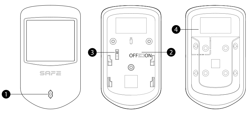
- LED indicator (green) – indicates pairing, alarm, and test results (see Signaling).
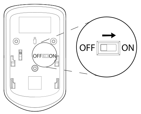
- Power switch (ON/OFF) – turns the device on and off.
- Tamper contact – triggers an alarm when the detector body is removed from the mounting plate.
- Rear cover – opening the rear cover triggers a tamper alarm; it hides the battery compartment.
Operating Principle
Motion Guard Plus detects a moving intruder in the protected area by combining two independent technologies – a dual PIR sensor and a microwave sensor (24 GHz). The alarm is triggered only when motion is confirmed by both technologies simultaneously. The detector thus reliably distinguishes real human movement from moving curtains, blind vibrations, drafts, or intense sunlight.
When an alarm is triggered, the detector immediately relays the event to the hub, and the user receives a notification in the ProSAFE.
Intelligent digital detection algorithm
The detector uses a digital signal processing algorithm that, based on analysis of infrared radiation and the microwave signal, accurately identifies relevant motion and adapts to various environmental conditions (changes in temperature, lighting, humidity). Resistance to white light is 2 000 lx.
PET immunity
The detector ignores the movement of animals up to a height of 50 cm and a weight of 18 kg. Your pets can therefore move freely around the room without triggering an alarm.
Temperature compensation
Bidirectional digital temperature compensation ensures that the detection distance does not decrease at high temperature. The built-in temperature sensor also measures the ambient temperature in the range of −15 °C to +65 °C with an accuracy of ±1 °C and allows you to set an unusual temperature alarm.
SAFE Keeper protocol
Communication with the hub is provided by the encrypted two-way radio protocol SAFE Keeper in the 868 MHz band:
- AES-128 encryption with a rolling code,
- frequency hopping as protection against interference – if the signal is jammed, it alerts the user and automatically retunes to an interference-free frequency band,
- range up to 1 600 m in open space,
- regular connection checks – the system immediately reports any detector outage.
Adding to the System
Before adding the device
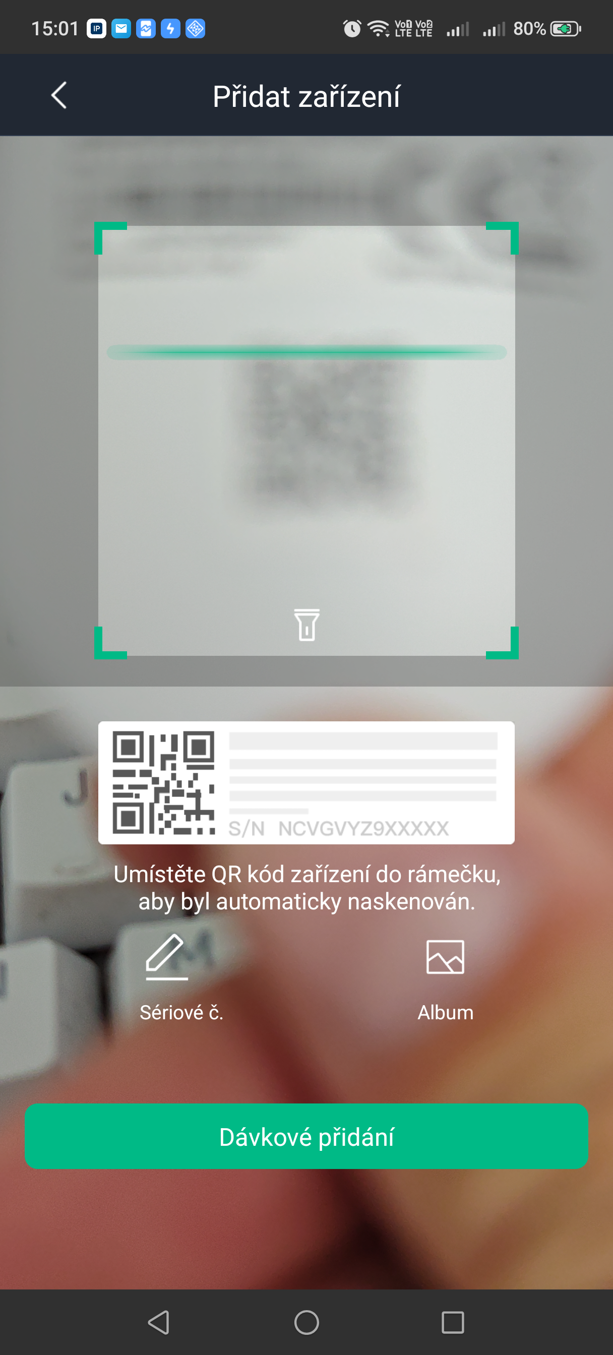
- Install the app ProSAFE and log in to your account.
- Make sure you have a compatible hub added in the app (Hub 2 Plus LTE, SAFE 38300) with a stable internet connection.
- The hub must be in the Disarmed state.
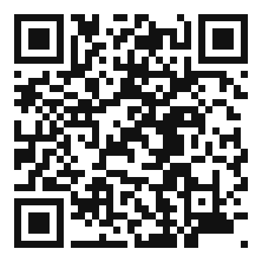
How to add Motion Guard Plus
- In the ProSAFE app, open your hub and click Device.
- Click + Add device.
- Scan the QR code with the serial number on the bottom of the detector and click Next.
- Once the detector is found, click Next.
- Following the on-screen instructions, open the rear cover of the detector and set the power switch to position ON, then click Next.
- Wait for pairing to complete – successful pairing is confirmed by the LED lighting up for 2 seconds.
- Enter the detector name, select the area (zone), and click Done.
States
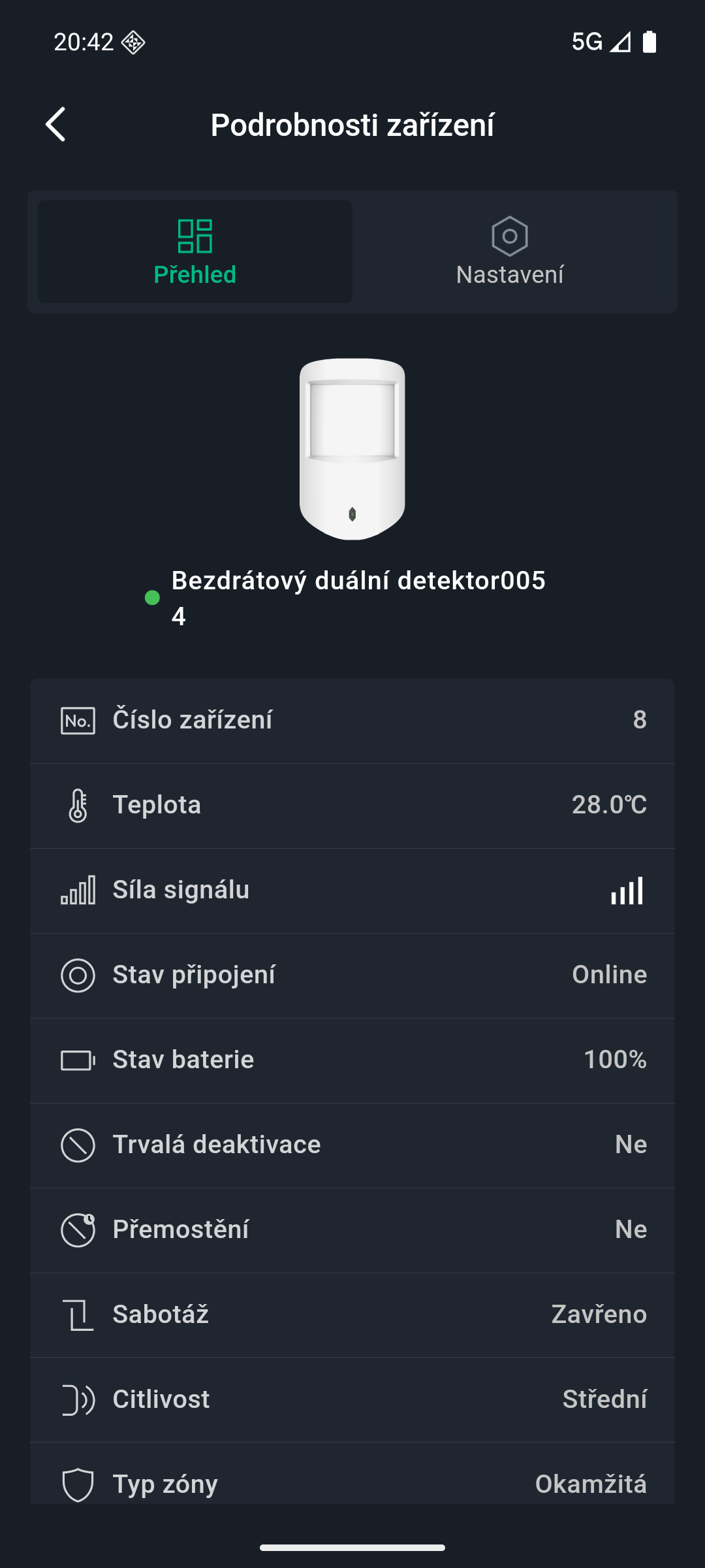
You can view the current detector status in the ProSAFE app by selecting the detector in the Devices list.
| Parameter | Meaning |
|---|---|
| Temporarily disable | Detector functional status
|
| Online status | Connection between the detector and the hub
|
| Signal strength | Radio signal level: none / low / weak / good / excellent |
| Battery level | Full / sufficient / medium / insufficient / low |
| Tamper status | Indicates that the detector has been removed from the mounting plate |
| Temperature | Current ambient temperature measured by the integrated sensor |
| Sensitivity | Set motion detection sensitivity level – the higher the value, the more easily motion is detected |
| 24-hour zone | Enabled / disabled – detection independent of the system's arming status |
| Entry / exit delay | The configured delay times for entry and exit |
| Transmission via repeater | Whether the detector communicates with the hub via a signal repeater |
| Firmware version | Current detector firmware version |
Settings
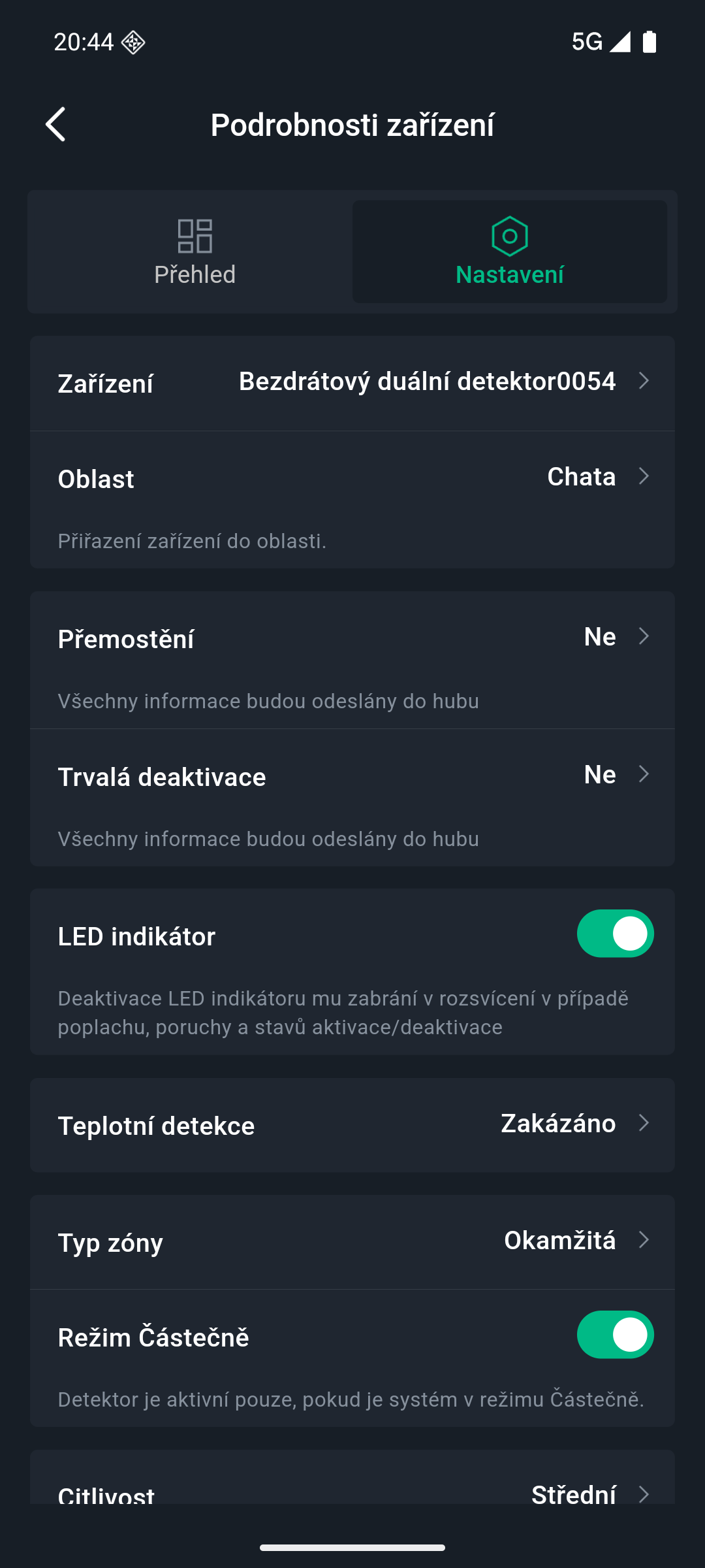
You can change the settings in the ProSAFE app: select the detector in the Devices list and click the edit icon.
| Settings | Value |
|---|---|
| Device name | Custom detector name; shown in the device list and in notifications |
| Area (zone) | Assigning the detector to a system area |
| Temporarily disable | Allow (default) / Disable tamper alarm only / Disable |
| LED indicator | On (default) / off – when off, the LED does not light up regardless of the device's status |
| 24-hour zone | Enabled – the detector monitors even when the system is disarmed. Disabled – the detector monitors only after the system is armed, with a delay until the end of the communication interval with the hub (default 60 s) |
| Sensitivity | Low / medium / high – choose based on the detection test results |
| Number of alarms | Number of alarms triggered during one system activation |
| Home Armed mode | Partial activation of selected devices under the hub |
| Delay in Home Armed mode | The alarm activates only after the delay has elapsed; can be enabled only when Home Armed mode is on |
| Delay | Entry delay max. 45 s (according to EN 50131-1), exit 0–120 s |
| Siren linkage | The siren sounds when this detector triggers an alarm |
| Alarm video | Linking the detector's alarm to a camera video channel in the system; video channel selection |
| Unusual temperature alarm | Alarm when the set temperature range (min/max) is exceeded |
| Transmission power | High / low / automatic – higher power extends range and increases consumption. Low power switches the detector to reduced sensitivity mode (LED flashes) – useful for signal testing during installation |
| Signal strength test | Verification of the radio connection quality at the installation site |
| Detector test | Verifies the detection function; starts by the end of the communication interval with the hub (default 60 s) |
| User Manual | Displaying the device manual |
| Cloud update | Remote firmware update |
| Remove device | Deleting the detector from the system (swipe left in the Devices list) |
Signaling
| LED indication | Event |
|---|---|
| Fast green blinking | Pairing mode, or reduced-sensitivity mode (low transmission power) |
| Lights up green for 2 s | Successful pairing with the hub |
| Slow green blinking for 3 s | Pairing failed |
| Continuously lit green | An alarm has been triggered |
| Fast green blinking for 100 s, then turns off | Confirmation of switching the transmit power to low (reduced sensitivity mode) |
| Off | The LED indicator is turned off in the settings, or the device is switched off |
Choosing the installation location
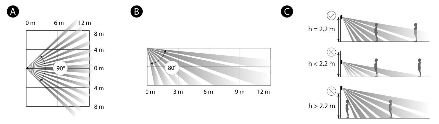
Position the detector so that its field of view covers the intruder's expected path (ideally perpendicular to the direction of movement) and no obstacles block the view. The recommended installation height is 2–2,4 m; the stated range of 12 m and field of view of 80–90° apply to an installation height of 2.2 m.
Signal strength
Before final installation, test the signal strength in the app (Signal strength test). If the signal is weak, move the detector or use a signal repeater.
Detection zone
The actual detection range may vary depending on ambient temperature and lighting. After installation, always perform a detector test and walk through the protected area – this verifies actual coverage. The stated range and field of view apply only if the recommended installation height of 2.2 m is maintained – at a lower or higher mounting position, the detection zone shifts and part of the area may not be covered.
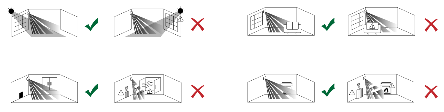
Where not to install the detector
- Facing a window exposed to direct sunlight or its reflections.
- In front of curtains, blinds, or other moving objects extending into the field of view.
- In locations where furniture or other obstacles block the field of view.
- Near heat sources – heaters, fireplaces, and other appliances.
Detector installation
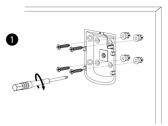
The detector can be mounted on a wall or in a corner using the included mounting kit (screws, wall plugs), or the included double-sided adhesive tape on a smooth and clean surface. Before drilling or gluing, we recommend temporarily attaching the detector at the installation location and performing a signal strength test and a detector test.
Wall Mounting
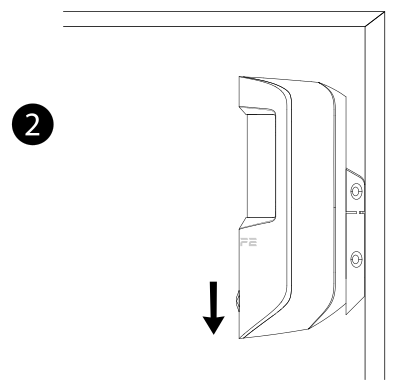
- Following the holes on the mounting plate, drill 4 holes into the wall and insert the wall plugs (included in the package), then screw the plate to the wall. Alternatively, attach the plate using double-sided adhesive tape.
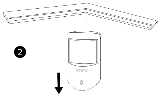
- Place the detector body onto the mounting plate by sliding it in the direction of the arrow.
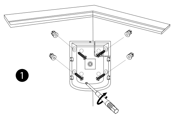
Corner mounting
- Drill 4 holes according to the spacing of the corner mounting holes, insert the wall plugs, and screw the plate into the corner. Alternatively, attach the plate using double-sided adhesive tape.
- Place the detector body onto the mounting plate by sliding it in the direction of the arrow.
Functionality Test
After installation, verify the correct function of the detector:
- Signal strength test – run a test in the app and verify the quality of the radio connection with the hub.
- Detector test – start the test and walk through the protected area; verify that the detector registered motion throughout the entire required zone. The test does not start immediately, but only at the end of the detector's communication interval with the hub (default 60 s).
Battery replacement
The detector is powered by 1× CR123A lithium battery (3 H) with a lifespan of up to 4 years. The battery is inserted in the device at the factory. The ProSAFE app will notify you of a low battery.
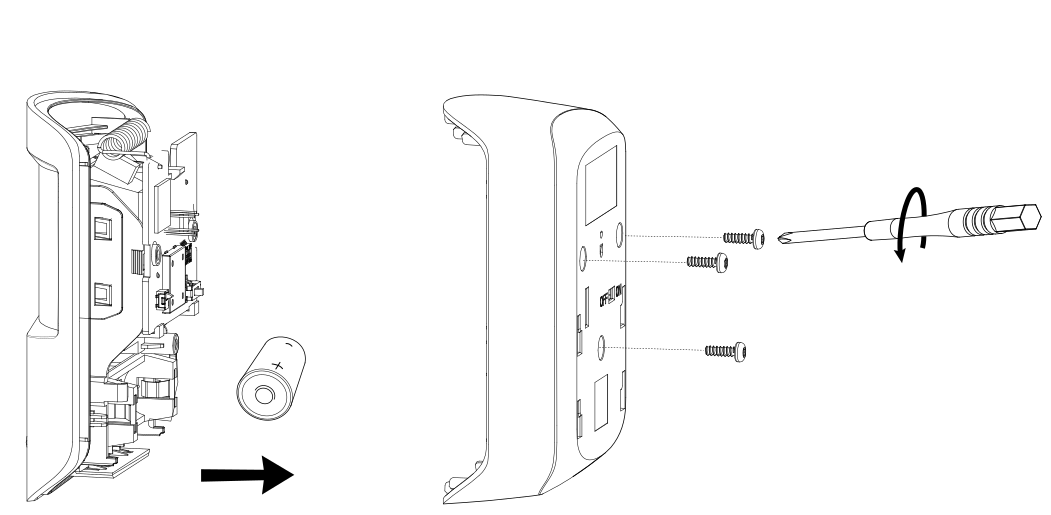
- Remove the detector body from the mounting plate and turn it off using the power switch.
- Loosen the screws on the back and open the rear cover.
- Remove the old battery and insert a new CR123A battery. Observe the correct polarity – the "+" symbol on the battery must match the symbol inside the detector.
- Close the rear cover and tighten the screws.
- Turn on the device using the switch, setting it to position ON.
- Place the detector back onto the mounting plate.
Maintenance
- Keep the lens and detector cover clean – wipe off dust with a dry, soft cloth. Do not use aggressive cleaning agents.
- Check that the field of view is not blocked by new furniture, decorations, or other obstacles.
- Regularly check the battery status and signal strength in the ProSAFE app.
- Perform a detector test again after every manipulation of the detector.
- Do not disassemble the detector and protect it from moisture and liquids.
Technical Specifications
| Detection parameters | |
| Detection type | Motion – dual PIR + microwave sensor |
| Sensor | Dual-element low-noise PIR sensor + microwave sensor |
| Microwave frequency | 24 GHz |
| Detection range | 12 m, 80–90° (at an installation height of 2.2 m) |
| Speed of the detected object | 0.3–3 m/s |
| PET immunity | Ignores animals up to a height of 50 cm and a weight of 18 kg |
| Resistance to white light | 2,000 lx |
| Sensitivity | Adjustable in 3 levels |
| Temperature compensation | Bidirectional digital, no reduction in detection distance at high temperature |
| Temperature sensor | |
| Measuring range | −15 °C to +65 °C (indoors) |
| Accuracy / resolution | ±1 °C / 1 °C |
| Wireless transmission – SAFE Keeper | |
| Carrier frequency | 868.0–868.6 MHz |
| Transmitter power (EIRP) | limit 25 mW |
| Communication distance | Up to 1,600 m in open space |
| Communication type | Two-way |
| Encryption | AES-128 with rolling code |
| Frequency hopping | Yes (anti-jamming protection) |
| Interface and functions | |
| Indication | 1× green LED |
| Control Devices | 1× power switch |
| Tamper contact | Yes |
| Remote update | Yes (cloud) |
| Low battery notification | Yes |
| Device search | Yes (signal strength detection) |
| Test mode | Signal strength test, detector test |
| General | |
| Power supply | 1× CR123A battery, 3 V (pre-installed at the factory) |
| Power consumption | Max. 615 mW |
| Current draw | ≤ 11 µA (standby), ≤ 71 mA (alarm) |
| Battery life | Up to 4 years |
| Operating temperature | −10 °C to +55 °C (indoors) |
| Operating humidity | 10–90 % RH |
| Housing material | PC + ABS |
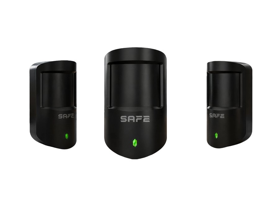
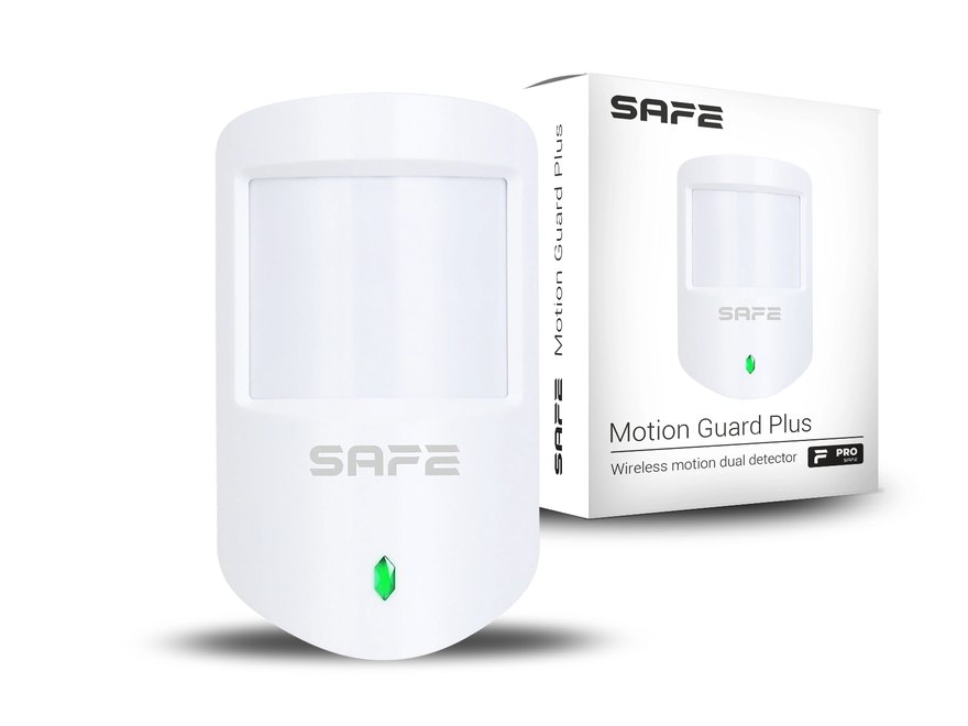
| Color | White (SAFE 38410) / black (SAFE 38411) |
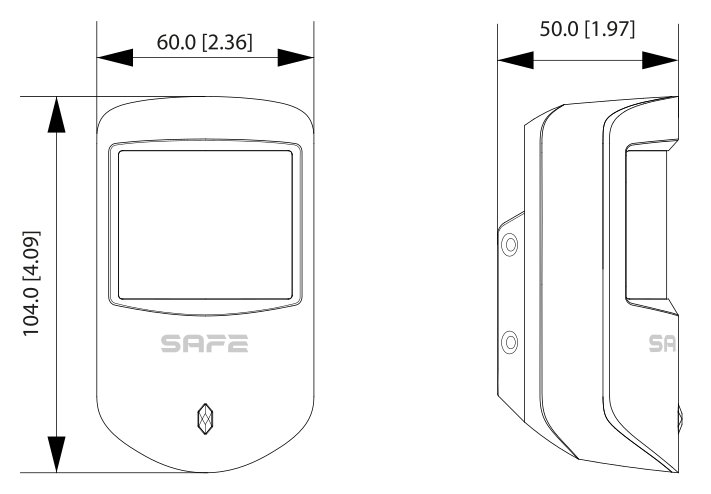
| Product dimensions | 104.0 × 60.0 × 50.0 mm |
| Package dimensions | 137.0 × 98.0 × 57.0 mm |
| Weight (net / gross) | 106 g / 192 g |
| Installation | On mounting plate (wall, corner); recommended height 2–2.4 m |
| Compatibility | Hub 2 Plus LTE (SAFE 38300) |
| Certification | CE; EN 50131-1; EN 50131-2-2; EN 50131-5-3; EN 50131-6; Security grade 2; Environmental class II |
Package Contents
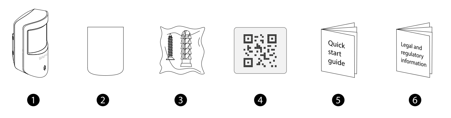
- Motion Guard Plus detector (CR123A battery pre-installed) – 1 pcs
- Double-sided adhesive tape – 1 pcs
- Mounting kit (screws, wall plugs) – 1 set
- QR code with the user manual – 1 pcs
- Quick user guide – 1 pcs
- Legal and regulatory information – 1 pcs
Safety Notices
- Operate and store the device only within the permitted temperature and humidity range; protect it from liquids.
- Do not install the device in places exposed to direct sunlight or near heat sources.
- Keep the battery out of the reach of children. Do not throw the battery into fire, crush it, or cut it – this may cause an explosion. If battery ingestion is suspected, seek medical help immediately.
- Replace a depleted battery only with a battery of the same type and model (CR123A).
- Do not dispose of the product with regular household waste – hand it in for recycling through the electrical equipment take-back system.
Warranty
The SAFE Motion Guard Plus device is covered by a warranty 36 months from the date of sale. The warranty does not cover the battery or defects caused by failure to follow the instructions in this manual.
If you experience any problems with the device, contact technical support first – most situations can be resolved remotely.
Gallery
Need Help?
SAFE HOME europe technical support:
Email: info@safe-home.eu · Phone: (+420) 581 222 262
Website: www.smart-safe.eu