
Foreword
Safety instructions
Revision history
Privacy Notice
About this guide
Precautions and warnings
Operational requirements
Installation requirements
Introduction
Overview
Technical Specifications
Package contents
Design
Description
Dimensions
Adding to the system
Installation
Detection Parameters
Battery replacement
Configuration
Status display
Detector configuration
Wired input configuration
Sensor
Sabotage
Key zone
Warranty
Wireless opening detector
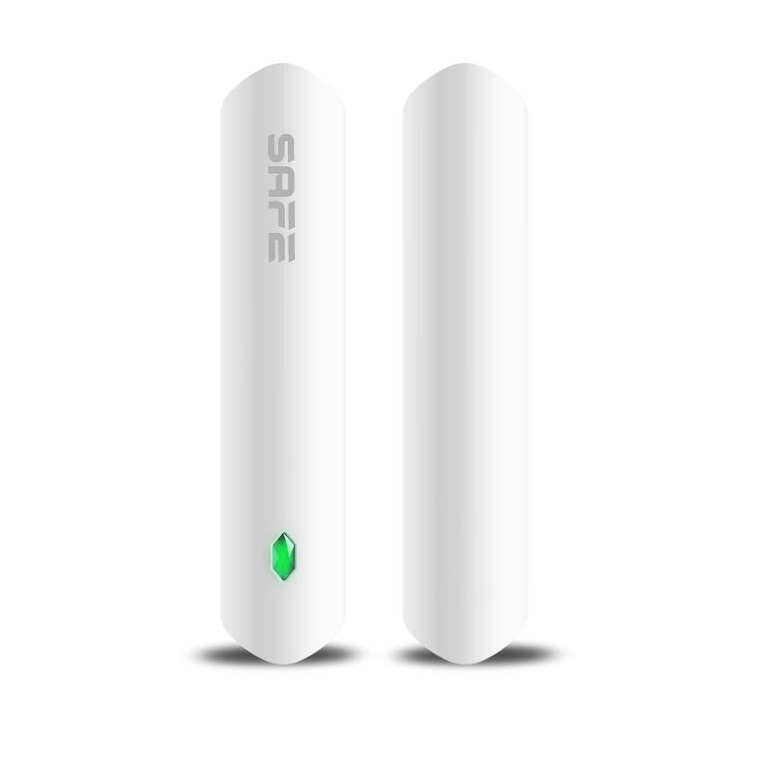
SAFE Door Guard (SAFE 38100)
Foreword
General
This user manual provides information on the installation, features and operation of the wireless opening detector (hereinafter referred to as the ‘detector’). Please read this manual carefully before using the device and keep it for future reference.
Safety instructions
The following signal words may appear in the user manual:
| Signal word | Meaning |
|---|---|
| DANGER | Indicates a high potential risk which may result in death or serious injury if not avoided. |
| WARNING | Indicates a medium or low potential hazard which could cause minor or moderate injury if not avoided. |
| NOTICE | Indicates a potential hazard that could result in property damage, data loss, reduced performance, or an unpredictable result. |
| TIP | It provides methods to help you solve a problem or save time. |
| NOTE | It provides additional information, such as highlighting and adding to the text. |
Revision history
| Version | Revision content | Date of publication |
|---|---|---|
| V1.0.0 | First edition | September 2024 |
Privacy Notice
About this guide
- This user guide is intended for reference purposes only. There may be minor differences between the information provided and the product itself.
- We accept no liability for damage resulting from the use of the product in a manner that does not comply with the instructions in the user manual.
- This guide will be updated in line with the latest laws and regulations in the relevant jurisdictions. Detailed information can be found in the printed user guide, by scanning the QR code, or on our official website. This guide is for reference purposes only. There may be minor differences between the electronic and printed versions.
- All designs and software are subject to change without prior written notice. Due to product updates, there may be some discrepancies between the product and the information in this manual. Please contact customer services for the latest version of the software and supplementary documentation.
- Errors or discrepancies may occur in the description of functions, operations and technical data in this document. In the event of any doubt or dispute, we reserve the right to provide the final interpretation. If you are unable to open the manual (in PDF format), please update your PDF reader software or try another standard PDF reader.
- All trade marks, registered trade marks and company names in this handbook are the property of their respective owners.
- If you encounter any problems whilst using the device, please visit our website, contact your supplier or customer services.
- In the event of any ambiguity or dispute, we reserve the right to provide a definitive explanation.
Important safety precautions and warnings
This section contains information on the correct handling of the product, risk prevention and the prevention of damage to property. Please read it carefully before using the equipment and follow the instructions provided when using it.
Operational requirements
⚠ NOTICE
- Before use, please ensure that the device’s power supply is working correctly.
- Do not unplug the device’s power cable whilst it is switched on.
- Only use the equipment within its rated power range.
- Transport, use and store the device within the permitted humidity and temperature ranges.
- Prevent liquids from splashing or dripping onto the device. Ensure that there are no objects containing liquid on the device to prevent liquids from entering it.
- Do not dismantle the device.
⚠ WARNING
- Connect the device to the power adapter before turning it on.
- Strictly comply with local electrical safety standards and ensure that the voltage in the area is stable and meets the device’s power supply requirements.
- Do not connect the device to more than one power source. Doing so may damage the device.
⚠ NOTICE
- When working at height, follow all safety procedures and use the required personal protective equipment made available to you.
- Do not expose the device to direct sunlight or sources of heat.
- Do not install the device in damp, dusty or smoky areas.
- Install the appliance in a well-ventilated area and do not block the device's vent.
- Use the mains adapter or power supply provided by the device manufacturer.
- The power supply must comply with the ES1 requirements of the IEC 62368-1 standard and must not exceed PS2.
- Please note that the power supply requirements are as stated on the device’s label.
- Connect Class I electrical appliances to a socket with a protective earth.
Introduction
Overview
The Door Guard wireless detector monitors the status of windows and doors and responds when they are opened. Additional devices with NO, NC or pulse outputs can be connected to the detector via an external contact. The device’s operating status is indicated by an LED indicator.
The detector forms part of the ProSAFE security system and is connected to the hub via the secure SafeKeeper communication protocol.
| Type | Parameter | Description |
|---|---|---|
| Interface | Indicator light | 1x green LED status indicator |
| Button | 1x power button | |
| Functions | Sabotage Contact | Yes (tamper) |
| Remote Update | Yes (Cloud) | |
| Search | Signal strength detection | |
| Test Mode | Yes | |
| Low Battery Warning | Yes | |
| Wireless Transmission | Carrier Frequency | 868.0 MHz – 868.6 MHz |
| Transmitter Power (EIRP) | Limit 25 mW | |
| Communication Distance | Up to 1,200 m (3,937.01 ft) in the open | |
| Communication Type | Bidirectional | |
| Encryption Mode | AES128 | |
| Frequency Hopping | Yes | |
| General | Power Supply | 1x CR123A battery (pre-installed) |
| Battery Voltage | 3 V DC | |
| Minimum voltage | 1.8 V DC | |
| Battery discharge threshold | 2.6 V DC | |
| Battery recharge threshold | 3.0 V DC | |
| Current Consumption | ≤ 12 μA (operation) / ≤ 2.3 mA (alarm) | |
| Power supply type | Type C | |
| Battery life | Up to 4 years (external NO input) Up to 2 years (external NC or pulse input) Detection twice a day when the battery efficiency is 70% | |
| Power Consumption | Max. 125 mW | |
| Operating environment | –10 °C to +55 °C (+14 °F to +131 °F) (indoors); Certified temperature range: -10 °C to +40 °C (+14 °F to +104 °F) | |
| Operating Humidity | 10 % – 90 % (RH) | |
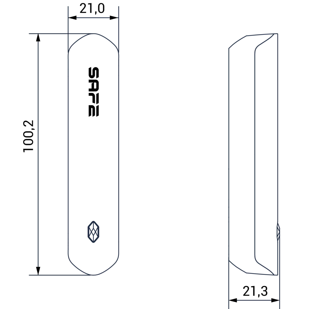
| Product Dimensions | 100.2 mm × 20.8 mm × 20.3 mm (3.94” × 0.82” × 0.80”) (L × W × H) | |
| Package Dimensions | 135.0 mm × 98.5 mm × 27.8 mm (5.31" × 3.88" × 1.09") (L × W × H) | |
| Weight (net) | 70 g (0.15 lb) | |
| Weight (gross) | 115 g (0.25 lb) | |
| Compliance | CE EN 50131-1:2006 + A1:2009+ A2:2017 + A3:2020 EN 50131-6:2017 EN 50131-5-3:2017 EN 50131-2-6:2008 Security level 2 Environmental class II | |
| Housing Material | PC + ABS | |
| Colour | White | |
| Compatibility | Hub v1.001.0000000.7.R.220106 or later | |
| Temperature Parameters | Measuring Range | –15 °C to +65 °C (+18.8 °F to +149 °F) (indoor areas) |
| Measurement Accuracy | ± 1 °C (± 33.8 °F) | |
| Resolution | 1 °C (33.8 °F) | |
| Detection Parameters | Detection Type | Magnetic |
| Sensor | Reed contact | |
| Detection Range | <40 mm (1.57") | |
| Inputs/Outputs | Alarm Input | 1 x NC/NO potential-free (adjustable) |
Package contents







| Number | Item name | Amount of pcs. |
|---|---|---|
| 1. | Wireless detector including a CR123A battery | 1 |
| 2. | Double-sided adhesive tape | 1 |
| 3. | Connection cable (external input) | 1 |
| 4. | Quick User Guide | 1 |
| 5. | Legal and regulatory information | 1 |
| 6. | Installation kit | 1 |
| 7. | QR code with the user guide | 1 |
Design
Description
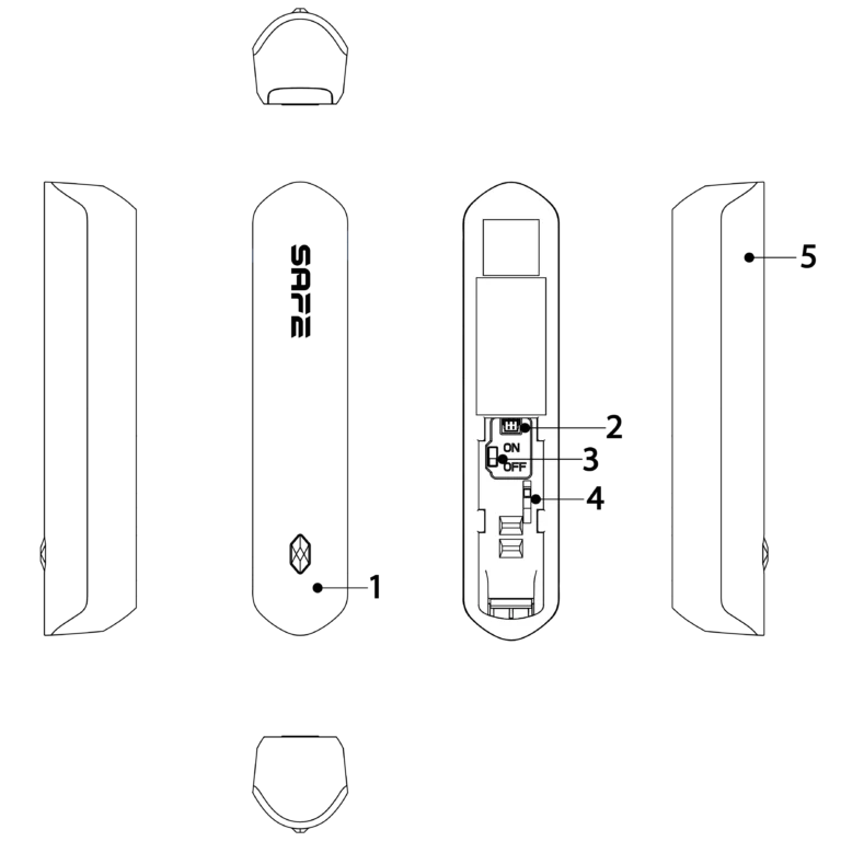
| N. | Name | Function description |
|---|---|---|
| 1 | LED Indicator | • Flashing green rapidly: Pairing mode or reduced sensitivity mode. • Continuous green light: Alarm (detection). • Steady green light for 2 seconds: Pairing successful. • Flashing slowly in green for 2 seconds: Pairing has failed. |
| 2 | Port for connecting an external device | Use the supplied connection cable to connect the devices. |
| 3 | On/Off switch | Detector power switch (ON = activated, OFF = deactivated). |
| 4 | Sabotage Contact | When the contact is disconnected, a tamper alarm is triggered. |
| 5 | Cover | Opening the cover will trigger a tamper alarm. |
Dimensions
Adding to the system
Prerequisites
The device is configured using the PRO Safe app. Please ensure that you have installed the PRO Safe app, created an account and added the hub to the app. For details on adding the hub, please refer to the user manual for the relevant hub.
📖 NOTE:
• Make sure the hub has a stable internet connection.
• Make sure the hub is deactivated (system deactivated).
• Make sure the detector is switched off (the power switch is in the OFF position).
Further information
This user guide uses operations in iOS as examples.
Procedure:
Step 1. In the app, go to the hub screen and tap the tab Device or Area.
Step 2. Tap the ‘(+)’ button in the top right-hand corner and select the option Add a peripheral device.
Next, enter the detector’s serial number using one of the options listed below:
- By using your mobile phone’s camera to scan the detector’s QR code (requires granting the app permission).
- Tap the [🌄] button in the top right-hand corner and select a photo of the detector’s QR code from your mobile phone’s gallery (this requires granting the app permission).
- By tapping the Enter SN manually button and adding the serial number manually.
Once you have found the detector, click the button Next.
Step 3. Follow the instructions in the app and switch on the detector when prompted. Then tap Next.
Step 4. Wait for the pairing to complete.
Step 5. Customise the detector name, select the area and tap Finish.
Installation
Before installing the detector, check the signal strength of the connection to the hub at the installation site using the mobile app. We recommend installing the detector in a location where the signal strength is at least 50% (at least 2 bars on the indicator).
⌚ TIP:
In the mobile app, go to the detector menu and run a detection test; before installation, first check the detection range between the detector and the magnetic component.
Procedure:
Step 1. Stick the double-sided adhesive tape (included in the pack) onto the detector’s mounting panel and the magnetic part.
Step 2. Mark and drill two holes in part no. 1 and two holes in part no. 2 of the window/door, in line with the positions of the holes on the mounting panel.
Step 3. Insert the wall plugs into the holes (optional, depending on the type of surface being fitted to). Align the screw holes in the mounting panel with the holes in the wall plugs.
Step 4. Secure the mounting panel using 3×18 mm screws (included in the pack).
Step 5. Fit both parts of the detector onto the mounting panel.
📖 NOTE:
You can also use the double-sided adhesive tape supplied to attach the detector and the magnetic part. Please bear in mind, however, that the adhesive will degrade over time and may cause the detector to fall off, resulting in permanent damage.
Always use suitable fasteners when installing the detector.

| N. | Description |
|---|---|
| 1 | Window/door section no. 1 |
| 2 | Window/door section no. 2 |
| 3 | 3x18 mm screw |
| 4 | Wall plugs |
| 5 | Mounting panel |
| 6 | Detector / magnetic component |
Detection parameters:
Opening
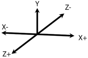
The detector will register an opening if the distance between it and the magnetic component exceeds the values shown in the table below.

| Axis of movement | Type of movement | Detection distance (mm) | Signal |
|---|---|---|---|
| Y | Moving away | 34 | V |
| Approaching | 28 | K | |
| X+ | Moving away | 20 | V |
| Approaching | 18 | K | |
| X- | Moving away | 20 | V |
| Approaching | 18 | K | |
| Z+ | Moving away | 46 | V |
| Approaching | 40 | K | |
| Z- | Moving away | 46 | V |
| Approaching | 39 | K |
Battery replacement
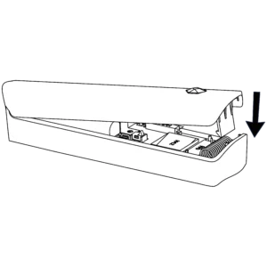
The battery is pre-installed at the factory and the detector is ready for immediate use. If the battery is flat, it must be replaced.
Procedure:
Step 1. Remove the detector from the mounting panel and switch it off.
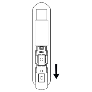
Step 2. Open the back cover (press the latch holding the cover in place).

Step 3. Replace the battery, ensuring that the polarity is correct.

Step 4. Close the rear cover, switch on the detector and fit it back into the mounting panel.
⚠ DANGER:
Keep new and used batteries out of the reach of children. Do not ingest the battery; there is a risk of chemical burns.
⚠ NOTICE:
The pre-installed battery provides up to 3 years of detector operation under normal use and standard operating conditions. More frequent use may reduce the battery life. You can check the current battery charge level at any time in the ProSAFE app.
Configuration
Viewing and editing general information about the detector.
Status display
To view information about the detector’s status, open the mobile app, go to the hub screen, select the detector from the list of peripherals, and go to the tab Overview.
📖 NOTE:
The detector has one input for connecting a wired device.
| Parameter | Value |
|---|---|
| Device number | The detector’s order in the system (based on pairing with the hub). |
| Temperature | The temperature measured by the detector’s sensor. |
| Signal strength | Hub connection signal strength indicator. |
| Connection status | Connection status between the detector and the hub. |
| Battery status | Detector battery charge level in %. |
| Permanent deactivation | The detector is in a permanently deactivated state. |
| Bridging | The detector is temporarily deactivated. |
| Sabotage | Status of the detector’s tamper contact. |
| Entry delay | The set entry delay time (if enabled). |
| Exit delay | The set exit delay time (if enabled). |
| External input | Status of the detector's external input. |
| Door detector status | Status of the magnetic opening detector. |
| Zone type | The currently selected zone type. |
| Chime | Status of the Chime function. |
| Connection via repeater | Use of a signal repeater for communication between the detector and the hub. |
| Device firmware version | Information about the current firmware version of the detector. |
Detector configuration
To change the detector configuration, open the mobile app, go to the hub screen, select the detector from the list of peripherals and go to the tab Settings.
| Parameter | Description |
|---|---|
| Device | Display of the detector name, type and serial number. • Tapping the “>” symbol in the device name field allows the name to be edited. Save the changes made by tapping the OK button in the upper right corner. |
| Area | Selection of the system area to which the detector is assigned. • Select the desired area from the list, or create a new one by tapping the Add area button. Save the changes made by tapping the OK button in the upper right corner. |
| Bridging | Temporary deactivation of the detector for one period of system arming / disarming. • Yes – Bypass enabled, information will not be transmitted to the hub. • Without tamper – Bypass enabled, information will be transmitted to the hub except for tamper alarms. • No – Bypass disabled, information will be transmitted to the hub. Save the changes made by tapping the OK button in the upper right corner. |
| Permanent deactivation | Permanent deactivation of the detector regardless of the system state. • Yes – Permanent deactivation enabled, information will not be transmitted to the hub. • Without tamper – Permanent deactivation enabled, information will be transmitted to the hub except for tamper alarms. • No – Permanent deactivation disabled, information will be transmitted to the hub. Save the changes made by tapping the OK button in the upper right corner. |
| LED Indicator | Enabling / disabling the detector's LED indicator. • Once disabled, the detector's LED indicator will not signal alarms, faults or system state changes. |
| Temperature Detection | Enabling / disabling the temperature detection function in the range of -10 °C to +55 °C. • If the set temperature limits are exceeded, an alarm is triggered. Save the changes made by tapping the OK button in the upper right corner. |
| Zone type | Selection of the detector zone type. • Instant – The alarm is triggered immediately after the detector is activated, if the system is armed. • Delay – The alarm is triggered after the set entry or exit delay time has elapsed. • 24-hour – The alarm is triggered immediately after the detector is activated, regardless of the system arming state. • Follower – The alarm is triggered immediately after the detector is activated, if the system is armed. If the detector is activated during the entry delay time, the alarm is triggered only after the set delay time has elapsed. If multiple delay zones are activated within one area, the alarm is triggered after the shortest delay time has elapsed. Save the changes made by tapping the OK button in the upper right corner. |
| Partial mode | Enabling / disabling detection in partial arming mode. • Enabled – The detector is active only in Partial mode. • Disabled – The detector is active in Arm mode. |
| Partial mode delay | Enabling / disabling the entry / exit delay function in Partial mode (option available only if the Delay zone type is selected). |
| Delay time | Setting the alarm triggering delay when entering and exiting the armed area within the range of 0 to 120 seconds. • Entry delay [s] – The alarm is triggered if the system is not disarmed before the set time elapses. • Exit delay [s] – The alarm is triggered if the user does not leave the armed area before the set time elapses. Save the changes made by tapping the OK button in the upper right corner. |
| Cross zone | Selection of a detector for assignment to a cross zone. The alarm is triggered only if both detectors are activated within the set time interval. Save the changes made by tapping the OK button in the upper right corner. |
| Interval | Setting the interval for cross zone activation within the range from 1 s to 1 h (option available only if the Cross zone function is enabled). Save the changes made by tapping the OK button in the upper right corner. |
| Alarm and video linkage | Enabling / disabling the function linking the detector alarm with a selected video channel. If enabled, a video recording from the selected video channel is saved after the detector triggers an alarm. |
| Video channel | Selection of the video channel for linking video and the detector alarm (option available only if the Alarm and video linkage function is enabled). • Select the desired video channel from the list. Save the changes made by tapping the OK button in the upper right corner. |
| Door detector configuration | Configuration of the magnetic opening detector parameters. • Door detector – Enabling / disabling the magnetic door detector function. • Door detector alarm indication by siren – Enabling / disabling siren alarm indication upon opening detection. Save the changes made by tapping the OK button in the upper right corner. |
| Chime | Enabling / disabling the Chime function. If enabled and the system is disarmed, the indoor siren emits a "ding-dong" sound when the opening detector is triggered. |
| Signal strength test | Test of the current signal strength between the detector and the hub. |
| Detection test | Test of the detector's detection. • The test does not start immediately. The detector switches to test mode within one ping interval of the status signal (see hub settings). |
| Transmitting power | Selection of the detector's radio signal transmitting power (high / low / automatic) • The higher the transmitting power, the farther the signal can travel, but the greater the power consumption. NOTE: If you select Low, the detector switches to reduced sensitivity mode until another option is selected. |
| User Guide | Searching in the detector user manuals. |
| Firmware Update | Information about the current firmware version of the detector. • If a new detector firmware update is available, tapping the Update button will download and install it. NOTE: The detector restarts during the update; some detector functions may be unavailable before the update is completed. |
| Remove | Option to remove the detector from the system (unpairing from the hub). TIP: To quickly remove the detector from the system, go to the hub screen, tap the “⋅⋅⋅” button next to the required peripheral in the peripherals list and select the Remove option. In the next step, confirm the removal by tapping the OK button. |
Wired input configuration
To configure the wired input, open the mobile app, go to the hub screen, select the detector from the list of peripherals and go to the tab Overview. Then tap the "+ Wired device" button located below the detector image. On the next screen, tap the button (+) in the upper right corner and fill in the required data (device name and area). Save the changes made by tapping the button OK in the upper right corner.
Once saved, the wired device can be configured as a sensor, tamper switch (tamper) or key zone.
Sensor
The connected external device serves as an independent detector for detecting intrusion, fire, distress, medical assistance calls, or water or gas leaks.
| Parameter | Description |
|---|---|
| Device | Displays the device name. • Tapping the “>” symbol in the device name field allows the name to be edited. Save the changes made by tapping the OK button in the upper right corner. |
| Area | Selection of the system area to which the device is assigned. • Select the desired area from the list, or create a new one by tapping the Add area button. Save the changes made by tapping the OK button in the upper right corner. |
| Bridging | Temporary device deactivation for the duration of one system arming / disarming period. • Yes – Bypass enabled, information will not be transmitted to the hub. • Without tamper – Bypass enabled, information will be transmitted to the hub except for tamper alarms. • No – Bypass disabled, information will be transmitted to the hub. Save the changes made by tapping the OK button in the upper right corner. |
| Permanent deactivation | Permanent device deactivation regardless of the system status. • Yes – Permanent deactivation enabled, information will not be transmitted to the hub. • Without tamper – Permanent deactivation enabled, information will be transmitted to the hub except for tamper alarms. • No – Permanent deactivation disabled, information will be transmitted to the hub. Save the changes made by tapping the OK button in the upper right corner. |
| External device type | Select the Sensor option. |
| Contact type | Selection of the output type of the connected device. • NC – normally closed. • NO – normally open. • Pulse – state change evaluation. |
| Alarm type | Selection of the device alarm type. • Intrusion alarm • Fire • Medical alarm • Panic alarm • Gas leak • Water leak Save the changes made by tapping the OK button in the upper right corner. |
| Zone type | Selection of the device zone type. • Instant – The alarm is triggered immediately after the device is activated, if the system is armed. • Delay – The alarm is triggered after the set entry or exit delay time has elapsed. • 24-hour – The alarm is triggered immediately after the device is activated, regardless of the system arming state. • Follower – The alarm is triggered immediately after the device is activated, if the system is armed. If the device is activated during the entry delay time, the alarm is triggered only after the set delay time has elapsed. If several delayed zones are activated within one area, the alarm is triggered after the shortest delay time has elapsed. Save the changes made by tapping the OK button in the upper right corner. |
| Partial mode | Enabling / disabling detection in partial arming mode. • Enabled – The device is active only in Partial mode. • Disabled – The device is active in Armed mode. |
| Partial mode delay | Setting the alarm triggering delay when entering and exiting the armed area within the range of 0 to 120 seconds. • Entry delay [s] – The alarm is triggered if the system is not disarmed before the set time elapses. • Exit delay [s] – The alarm is triggered if the user does not leave the armed area before the set time elapses. Save the changes made by tapping the OK button in the upper right corner. |
| Chime | Enabling / disabling the Chime function. If enabled and the system is disarmed, the indoor siren emits a "ding-dong" sound when the connected device is activated. |
| Cross zone | Selecting a detector for pairing into a cross zone. An alarm is triggered only if both devices are activated within the set time interval. Save the changes made by tapping the OK button in the upper right corner. |
| Interval | Setting the interval for cross zone activation in the range from 1 s to 1 h (option available only if the Cross zone function is enabled). Save the changes made by tapping the OK button in the upper right corner. |
| Alarm indication by siren | Enabling / disabling alarm signalling by the siren upon detection. |
| Alarm and video linkage | Enabling / disabling the function linking the device alarm with the selected video channel. If enabled, when the device triggers an alarm, a video recording from the selected video channel is saved. |
| Video channel | Selection of the video channel for linking video with the device alarm (option available only if the Alarm and video linkage function is enabled). • Select the desired video channel from the list. Save the changes made by tapping the OK button in the upper right corner. |
| Detection test | Device detection test. The test does not start immediately. The detector switches to test mode within one ping interval of the status signal (see hub settings). |
| Remove | Option to remove the device from the system (unpairing from the hub). |
Sabotage
The connected external device is used to detect unauthorised manipulation (e.g. opening the device cover).
| Parameter | Description |
|---|---|
| Device | Displaying the detector name. • Tapping the “>” symbol in the device name field allows the name to be edited. Save the changes made by tapping the OK button in the upper right corner. |
| Area | Selection of the system area to which the detector is assigned. • Select the desired area from the list, or create a new one by tapping the Add area button. Save the changes made by tapping the OK button in the upper right corner. |
| Bridging | Temporary deactivation of the detector for one period of system arming / disarming. • Yes – Bypass enabled, information will not be transmitted to the hub. • Without tamper – Bypass enabled, information will be transmitted to the hub except for tamper alarms. • No – Bypass disabled, information will be transmitted to the hub. Save the changes made by tapping the OK button in the upper right corner. |
| Permanent deactivation | Permanent deactivation of the detector regardless of the system state. • Yes – Permanent deactivation enabled, information will not be transmitted to the hub. • Without tamper – Permanent deactivation enabled, information will be transmitted to the hub except for tamper alarms. • No – Permanent deactivation disabled, information will be transmitted to the hub. Save the changes made by tapping the OK button in the upper right corner. |
| External device type | Select the Tamper option. |
| Contact type | Selecting the output type of the connected detector. • NC – normally closed. • NO – normally open. |
| Partial mode | Enabling / disabling detection in partial arming mode. • Enabled – The detector is active only in Partial mode. • Disabled – The detector is active in Arm mode. |
| Alarm indication by siren | Enabling / disabling alarm signalling by the siren upon detection. |
| Remove | Option to remove the device from the system (unpairing from the hub). |
Key zone
The connected external device is used to switch the security state of the system or selected areas (e.g. a key switch).
| Parameter | Description |
|---|---|
| Device | Displaying the detector name. • Tapping the “>” symbol in the device name field allows the name to be edited. Save the changes made by tapping the OK button in the upper right corner. |
| Area | Selection of the system area to which the detector is assigned. • Select the desired area from the list, or create a new one by tapping the Add area button. Save the changes made by tapping the OK button in the upper right corner. |
| Bridging | Temporary deactivation of the detector for one period of system arming / disarming. • Yes – Bypass enabled, information will not be transmitted to the hub. • Without tamper – Bypass enabled, information will be transmitted to the hub except for tamper alarms. • No – Bypass disabled, information will be transmitted to the hub. Save the changes made by tapping the OK button in the upper right corner. |
| Permanent deactivation | Permanent deactivation of the detector regardless of the system state. • Yes – Permanent deactivation enabled, information will not be transmitted to the hub. • Without tamper – Permanent deactivation enabled, information will be transmitted to the hub except for tamper alarms. • No – Permanent deactivation disabled, information will be transmitted to the hub. Save the changes made by tapping the OK button in the upper right corner. |
| External device type | Select the Key zone option. |
| Contact type | Selecting the output type of the connected wired device. • NC – normally closed. • NO – normally open. |
| Area permissions | Selecting the areas whose security mode is controlled by the key zone. • By enabling the All areas function, you select all areas in the system. Save the changes made by tapping the OK button in the upper right corner. |
| Control type | Selecting the key zone type. • Button – changing the security mode by a pulse (e.g. by pressing a button). • Switch – changing the security mode by switching the state (e.g. by flipping a switch). |
| Mode | Selecting the behaviour of the system or areas after the key zone is activated. • Arm/Disarm – switching the security mode between Armed and Disarmed states (option available if the Button control type is selected). • Partial/Disarm – switching the security mode between Partial and Disarmed states (option available if the Button control type is selected). • Arm – switching the security mode to the Armed state (option available if the Switch control type is selected). • Partially armed – switching the security mode to the Partial state (option available if the Switch control type is selected). • Disarm – switching the security mode to the Disarmed state (option available if the Switch control type is selected). |
| Forced arming | Enabling / disabling the Forced arming function. If enabled, the system or selected areas can be armed even with detected faults (e.g. low battery, open window). |
| Remove | Option to remove the device from the system (unpairing from the hub). |
Maintenance:
- To clean the detector body, use any agent suitable for its maintenance.
- Do not use any substances containing alcohol, acetone, petrol or other active solvents to clean the device.
Disposal

Do not dispose of electrical appliances as unsorted municipal waste; use separate waste collection points. Contact your local authorities for current information on collection points. If electrical appliances are disposed of in landfills, hazardous substances can leak into the groundwater and enter the food chain, damaging your health.
Warranty
- The manufacturer warrants that, under normal use and operation, the device specified will be free from any defects in material and workmanship for a period of three years (excluding batteries) from the date of sale. The manufacturer's obligation under this warranty is limited to the repair or replacement of the product or any of its parts which it finds defective in material or workmanship, free of charge, after it has been sent together with proof of the date of purchase and with postage prepaid to the address of the service centre: SAFE HOME europe s.r.o., Čechova 1005/4, 750 02 Přerov, Czech Republic.
- This warranty becomes void if the product has been damaged, altered, misused, modified after purchase, or if it has ceased to function as a result of poor maintenance or incorrect placement.
- Any implied warranties arising from this sale, including but not limited to implied warranties of description, merchantability and fitness for a particular purpose, are limited to the duration of this warranty.
- Under no circumstances shall the manufacturer or any of its parent, affiliated companies, or our sales representative or distributor be liable for loss of functionality of this product, nor for any indirect, special, incidental or consequential damage, or for costs or expenses incurred by the consumer or any other user of this product, whether due to breach of contract, negligence, strict liability in tort, or for other reasons.
- Neither the manufacturer nor any of its parent, subsidiary companies, or our sales representative or distributor shall be liable for any personal injury, property damage, or for any other special, indirect, incidental, or consequential damage arising out of the use of the product.
- This warranty does not affect your statutory rights.
- If the device does not work properly, we recommend contacting our technical support first. In most cases, technical problems can be resolved remotely.
- Current information regarding warranties, certificates, attestations, and other documents can also be found on our website: smart-safe.eu
- Technical support (Monday – Friday, 08:00 – 16:00): podpora@safe-home.eu