
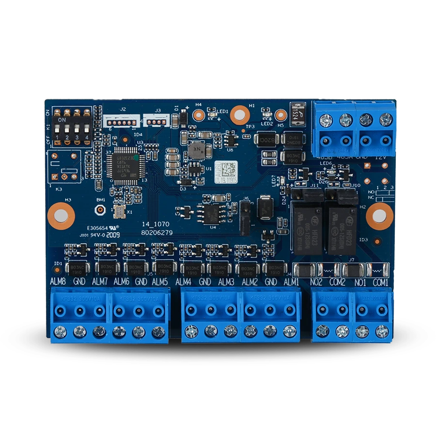
SAFE IO Expander Board extends the security system with eight wired inputs a two relay outputs. With the Hub 2 Plus LTE it communicates over the bus RS-485 via the Serial Bridge converter, turning a purely wireless Hub into a hybrid one. One bus can have up to 16 modules, so the capacity can be built up as needed. Each zone can be set separately – from a simple contact to a triple end-of-line resistor that distinguishes an alarm, tamper and a cable break.
Foreword
General
This user manual describes the installation, functions and operation of the hybrid input and output expander (hereinafter the “module”). Read the manual carefully before using the device and keep it for future reference.
Safety instructions
The following signal words may appear in the user manual:
| Signal word | Meaning |
|---|---|
| NEBEZPEČÍ | Indicates a high potential hazard which, if not avoided, may result in death or serious injury. |
| VAROVÁNÍ | Indicates a medium or low potential hazard which, if not avoided, could result in minor or moderate injury. |
| UPOZORNĚNÍ | Indicates a potential risk which could lead to property damage, data loss, reduced performance or an unpredictable result. |
| TIP | Provides methods to help you solve a problem or save time. |
| POZNÁMKA | Provides additional information, such as emphasis or a supplement to the text. |
Revision history
| Version | Revision content | Release date |
|---|---|---|
| V1.0.0 | First release. | September 2026 |
| V1.0.1 | Added illustrations from the graphic designer. | October 2026 |
Privacy notice
As a user of the device or a data controller, you may collect the personal data of others, such as their face, fingerprints and licence plate number. You must comply with local privacy protection laws and regulations in order to protect the legitimate rights and interests of other people by taking measures which include, but are not limited to: providing clear and visible identification to inform people of the existence of the monitored area and providing the required contact information.
About the manual
- The user manual serves as a reference only. Minor differences may occur between the information provided and the product.
- We are not liable for damage resulting from use of the product in a manner that is not in accordance with the instructions in the user manual.
- The manual will be updated in line with the current laws and regulations of the relevant countries. For detailed information, see the printed user manual, scan the QR code or visit our website. The manual is for information purposes only. The electronic and printed versions may differ in minor details.
- All designs and software may be changed without prior written notice. As a result of product updates, certain differences may appear between the product and the information in the manual. The latest version of the software and supplementary documentation is available from customer service.
- Printing errors or deviations may occur in the description of functions, operations and technical data. In case of doubt or dispute, we reserve the right of final interpretation. If the manual (in PDF format) cannot be opened, update your reader software or try another common reader.
- All trademarks, registered trademarks and company names in the manual are the property of their respective owners.
- If any problems occur while using the device, visit our website, or contact your supplier or customer service.
- In case of ambiguity or dispute, we reserve the right of final interpretation.
Important precautions and warnings
This section contains information on the correct handling of the product, risk prevention and prevention of property damage. Read it carefully before using the device and follow the instructions provided while using it.
Operating requirements
- Before use, make sure the device's power supply is working properly.
- Do not unplug the device's power cable while it is switched on.
- Use the device only within its rated power range.
- Transport, use and store the device under the permitted humidity and temperature conditions.
- Prevent liquids from splashing or dripping onto the device. Make sure there are no objects filled with liquid on the device, to prevent liquids from entering it.
- Do not disassemble the device.
Installation requirements
- Connect the device to the power adapter before switching it on.
- Strictly comply with local electrical safety standards and make sure the voltage in the area is stable and matches the device's power requirements.
- Do not connect the device to more than one power source. Otherwise, the device could be damaged.
- When working at height, follow all safety procedures and use the required protective equipment.
- Do not expose the device to direct sunlight or sources of heat.
- Do not install the device in damp, dusty or smoky locations.
- Install the device in a well-ventilated location and do not block its ventilation.
- Use the power adapter or power supply provided by the device manufacturer.
- The power supply must meet the ES1 requirements of IEC 62368-1 and must not exceed PS2. The power supply requirements are governed by the device's rating label.
- Connect Class I electrical appliances to a socket with protective earthing.
Functional elements
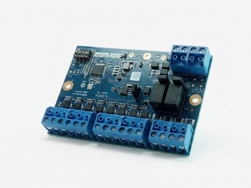
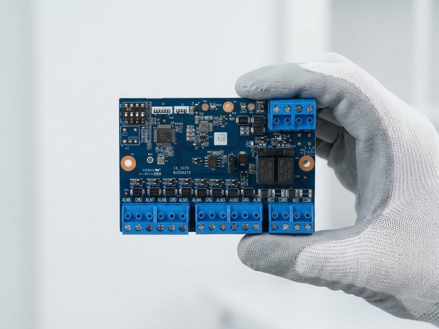
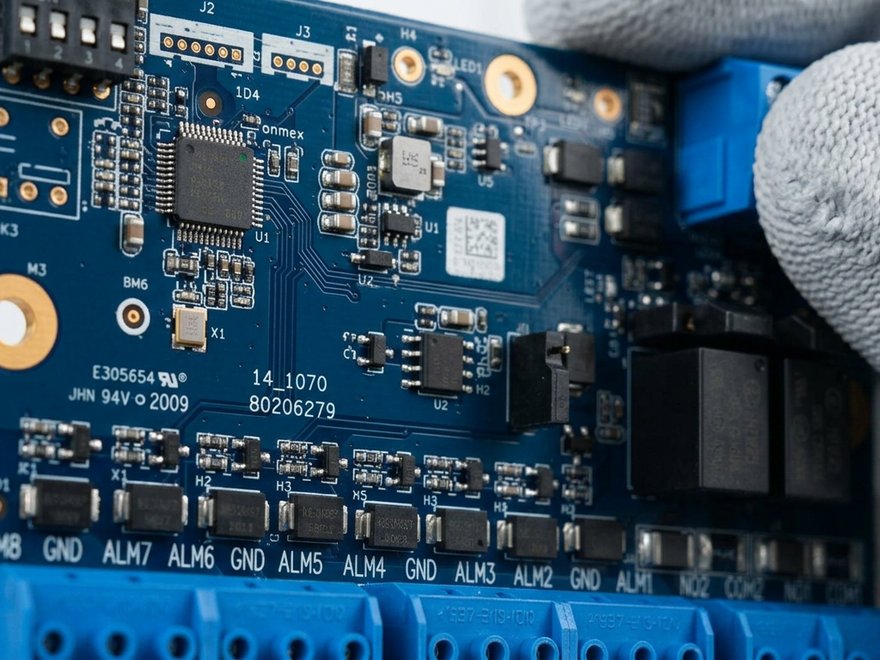
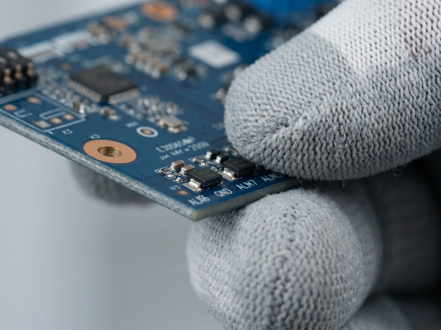
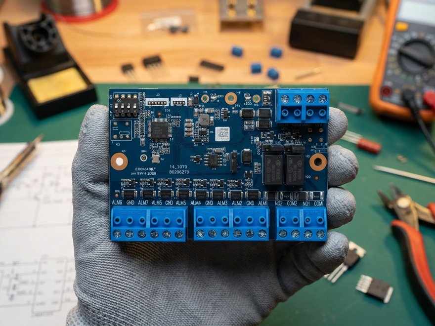
The module is a populated printed circuit board with screw terminal blocks around its edge. The labels on the board correspond to the designations in the terminal tables below.
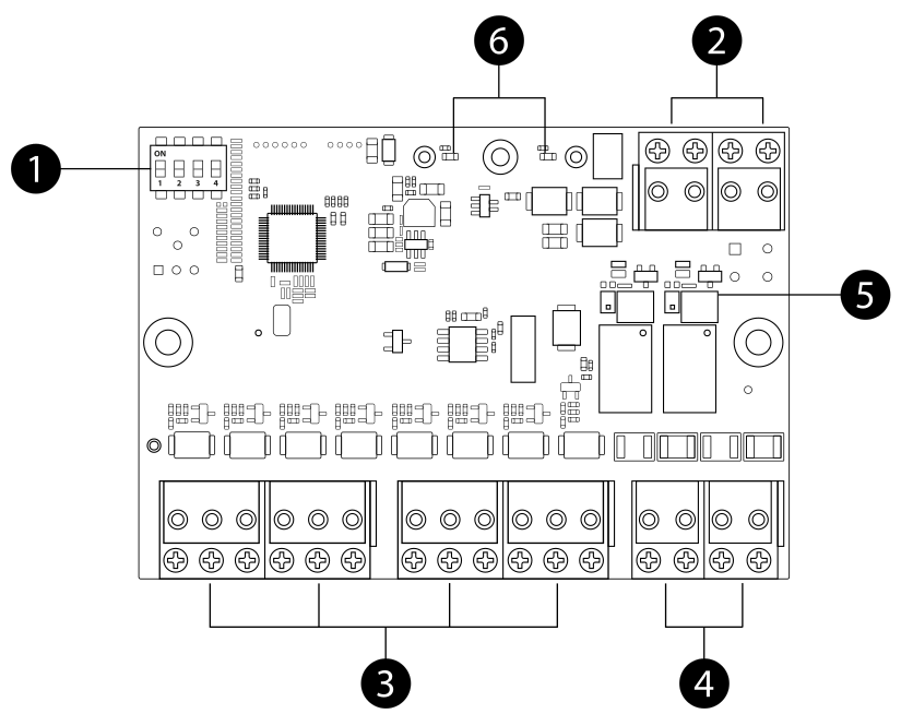
- DIP switch K1 (top left) – four positions used to set the module address on the bus. The up position is ON.
- Power and bus terminal block (top right) – 485B, 485A, GND, 12V.
- Alarm input terminal block (bottom left) – ALM1 up to ALM8 with common terminals GND.
- Relay output terminal block (bottom right) – NO1/COM1 a NO2/COM2.
- Jumpers J10 and J11 – mode selection of both outputs between NO a NC; the legend is printed on the board next to them.
- LED indicators – indicate the power and operation of the module.
Principle of operation
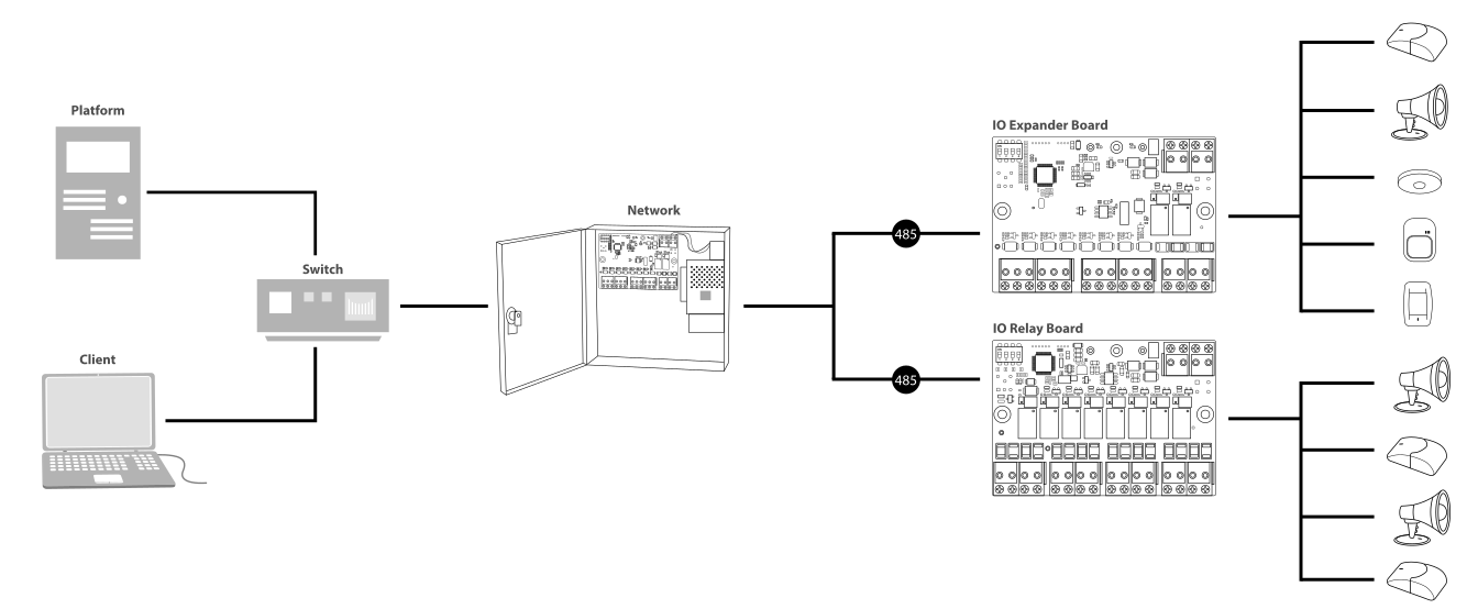
SAFE IO Expander Board extends the system with eight wired alarm inputs a two relay outputs. With the Hub 2 Plus LTE communicates over the RS-485 bus via the converter Serial Bridge. A purely wireless Hub thus becomes a hybrid one. The module needs no power supply or configuration of its own; it draws power from the port it is plugged into.
Integration of existing wired elements
Practically any wired security or automation device can be connected to the inputs – PIR motion detectors, magnetic contacts, sensors, thermostats or fire alarms, including those from other manufacturers. Each connected device is individually addressable and configurable in the system, so an existing wired installation can be taken over without being changed.
Zone configuration
Each input is set separately. The module supports the wiring NC, NO, 1EOL, 2EOL a 3EOL and also inertial and pulse modes; both pulse and bistable devices can be connected. End-of-line resistors are fitted to the terminals; the supported values are 2.7 kΩ, 4.7 kΩ and 6.8 kΩ. The line resistance is measured automatically during installation, which saves time and makes the configuration more accurate.
Relay outputs
The two outputs can be switched with a jumper between normally closed and normally open contact (NC / NO) and loaded up to 30 V DC / 500 mA. They are used to activate sirens and beacons, shut off the water or gas supply, or control automation elements and electronic door locks.
Types of alarm events
Each input is assigned an event type with which the alarm is reported to the app and to the DPPC – intrusion, panic alarm / SOS, fire, medical alarm, gas leak or water leak. From the notification, the operator can thus tell not only the location but also the type of incident.
Automation scenes
Events from connected devices can trigger SAFE system scenes – lock the doors, switch on the lights, disconnect appliances. They can be linked with other elements of the system, for example Power Relay, Dry Relay or Socket.
Firmware update
The module firmware is updated remotely using client software, so the module does not have to be dismounted for this purpose.
Bus connection
All four terminals are in one terminal block at the top right of the board. The module communicates with the Hub Hub 2 Plus LTE over the bus RS-485. The Hub has an RS-232 serial port on its board, so a converter is inserted between them SAFE Serial Bridge. Without it the module cannot be connected to the Hub.
| Terminal | Wiring |
|---|---|
| 12V | Positive pole of the 12 V DC power supply |
| GND | Negative pole of the power supply, common ground |
| 485A | Bus wire A – to the same branch as the other modules |
| 485B | Bus wire B |
How many modules per bus
The Hub bus can have up to up to 16 modules – in any combination IO Expander Board a IO Relay Board. You can therefore build up the capacity as needed: sixteen expanders give 128 wired inputs, sixteen relay boards 128 outputs.
Address setting
The board has a DIP switch, used to assign the module an address on the bus. Each module must have a different address; two modules with the same address interfere with each other and the system will not find them.
| Parameter | Value |
|---|---|
| Number of addresses | 16 – this is how many modules one bus can carry |
| Settings | By the combination of DIP switch positions on the board |
| Switch order | The address is read from the most significant bit to the least significant (H → L), as marked on the board |
| When to set | Before connecting power; after changing the address, disconnect the module and connect it again |
Input wiring
The inputs are labelled on the board ALM1 up to ALM8. Between them are common terminals GND, which neighbouring zones share – a single detector is therefore connected between its ALM terminal and the nearest GND. The wiring method depends on the detector type and the selected line configuration.
| Line type | Description |
|---|---|
| NC | Normally closed contact without end-of-line resistor |
| NO | Normally open contact without end-of-line resistor |
| 1EOL | One end-of-line resistor – distinguishes an alarm and a line break |
| 2EOL | Two resistors – additionally distinguishes detector tamper |
| 3EOL | Three resistors – additionally distinguishes a short circuit and masking |
| Inertial mode | For shock and inertia detectors |
| Pulse mode | For detectors with a pulse output |
Output wiring
The module has two relay outputs. The mode is selected with a jumper on the board, not in the app.
| Parameter | Value |
|---|---|
| Number of outputs | 2 |
| Terminals | NO1 / COM1 a NO2 / COM2 |
| Mode | NO or NC, switchable with jumper J10 (output 1) and J11 (output 2) |
| Load rating | 30 V DC / 500 mA |
| Operating mode | Pulse or bistable |
Choosing the installation location
The module is intended for indoor environments, for installation in a junction box or distribution board. Place it so that the bus and power supply can be routed to it and so that it remains accessible for any change of address.
Where not to install the module
- In damp, dusty or smoky areas, or in places where condensation is likely.
- In direct sunlight or near heat sources.
- Next to power wiring and appliances that cause interference – route the bus separately from power conductors.
- In places where it would be freely accessible to unauthorised persons.
Installation
- Disconnect the power supply of the Hub and the module's power supply.
- Fix the board in a junction box or distribution board so that its underside does not touch a conductive surface.
- Set the module address with the DIP switch.
- Use the jumpers to select the mode of both relay outputs (NO or NC).
- Connect the bus 485 A a 485 B and the power supply +12V / GND.
- Connect the detectors to the input terminals, including the end-of-line resistors, and connect the controlled elements to the outputs.
- Connect the power supply and verify in the system that the module has reported itself and that the zones report the correct idle state.
Maintenance
- Check the tightness of the terminals from time to time – a loose wire shows up as random zone faults.
- Do not clean the board with liquids; remove dust with dry compressed air.
- Before handling it, discharge yourself by touching an earthed object.
- Keep the module firmware up to date.
Technical specifications
| Interface | |
| Inputs | 8 alarm input channels (programmable) |
| Outputs | 2 alarm output channels (relay, NO/NC selection by jumper) |
| Communication interface | RS-485; cabling up to max. 300 m, cable type e.g. RVV 2 × 1.5 |
| Addressing | Adjustable using the DIP switch |
| Connection capacity | Max. 16 modules (IO Expander Boards, IO Relay Boards or a combination of them) |
| Optical indication | 1× built-in LED indicator |
| Functions | |
| Line configuration | NC, NO, 1EOL, 2EOL, 3EOL, inertial and pulse |
| EOLR support | 2.7 kΩ; 4.7 kΩ; 6.8 kΩ |
| Operating mode | Pulse, bistable |
| Output load rating | 30 V DC / 500 mA |
| Update | Remote update using client software |
| General | |
| Power supply | 12 V DC |
| Power consumption | 1,2 W |
| Operating temperature | −10 °C to +55 °C |
| Operating humidity | 10 % – 90 % RH, non-condensing |
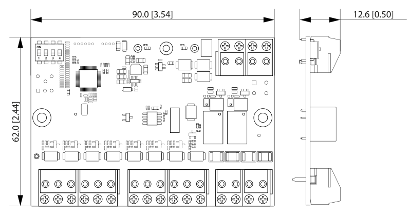
| Dimensions | 90.0 × 62.0 × 12.6 mm |
| Weight (net) | 0.52 kg |
| Installation | In a junction box |
| Compatibility | Hub 2 Plus LTE SAFE 38300; Serial Bridge SAFE 38181; IO Relay Board SAFE 38183 |
| Compliance | CE; EN 55032:2015+A1:2020; EN 61000-3-2:2019+A1:2021+A2:2024; EN 61000-3-3:2013+A1:2019+A2:2021; EN 55035:2017+A11:2020; EN 50130-4:2011+A1:2014; IEC 62368-1:2023 / EN IEC 62368:2024+A11:2024; EN IEC 63000:2018 |
| Model designation | SAFE 38182 |
| EAN code | 0728204235195 |
Package contents
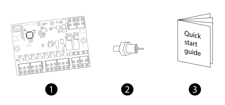
- SAFE IO Expander Board module – 1 pc
- End-of-line resistor set – 1 set
- Quick user guide – 1 pc
Safety notices
- The module is intended for indoor environments and for the permitted temperature and humidity range (−10 °C to +55 °C, 10 % – 90 % RH, non-condensing).
- Always disconnect the power supply – of the Hub and of the module – before wiring.
- Fit the end-of-line resistors according to the design; an incorrect value makes it impossible to distinguish an alarm from a line fault.
- Do not disassemble the device or interfere with the printed circuit board; protect it from moisture, dust and static electricity.
- Observe local electrical regulations. Have the connection to the mains wiring carried out by a qualified electrician.
- Do not dispose of the product with ordinary municipal waste – hand it in for recycling in the electrical equipment take-back system.
Warranty
A warranty is provided on the SAFE IO Expander Board device 36 months from the date of sale. The warranty does not cover defects caused by failure to follow the instructions given in this manual.
In case of problems with the device, first contact technical support – most situations can be resolved remotely.
Gallery
Need help?
SAFE HOME europe technical support:
E-mail: info@safe-home.eu · Telephone: (+420) 581 222 262
Web: www.smart-safe.eu